
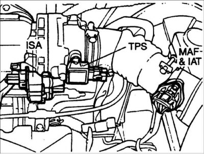
Placement of MFI control system elements
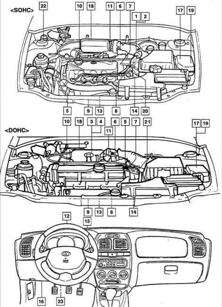
1 – air flow meter "OBD"; 2 – engine inlet air temperature sensor; 3 – air flow meter, except "OBD"; 4 – air-fuel ratio sensor, except "OBD"; 5 – coolant temperature sensor; 6 – throttle position sensor; 7 – camshaft position sensor; 8 – crankshaft angle sensor; 9 – heated oxygen sensor; 10 – fuel injectors; 11 – idle speed modulator; 12 – vehicle speed sensor; 13 – knock sensor; 14 – Gearbox range switch; 15 – ignition switch; 16 – Engine control unit ECM; 17 – Air conditioning system relay; 18 – electromagnetic valve for cleaning the canister with activated carbon; 19 – MFI main relay; 20 – ignition coils; 21 – fuel pump; 22 – acceleration sensor; 23 – diagnostic connector.
The fuel system is controlled by the engine control unit ECM (Engine Control Module). The ECM controls the ignition timing, determines the amount of fuel supplied to the engine, controls the exhaust gas toxicity reduction system and the engine idle speed, as well as the air conditioning compressor clutch, etc. The ECM changes the engine operating modes depending on changing operating conditions based on signals from various switches and sensors.
For example, the ECM adjusts the ignition timing based on signals from sensors that respond to engine speed, coolant temperature, throttle position, current gear position, vehicle speed, etc.
The ECM regulates the idle speed based on signals from sensors that respond to the throttle position, vehicle speed, the current gear engaged, etc.
Air Flow Meter Sensor "OBD" (MAF – Mass Airflow Sensor)
The air flow meter provides the most direct method of measuring engine loads, as it measures the amount of air entering the engine. Air flow enters the engine through a meter with a hot and cold wire element, which forms part of a bridge circuit. Current passing through the hot wire element maintains its constant temperature at a constant level, which is higher than the temperature of the air entering the engine. The air mass is determined by the current required to maintain the wire element temperature. The greater the air flow and, naturally, its cooling, the greater the signal magnitude sent to the ECM.
Engine Air Temperature Sensor "OBD" (IAT – intake air temperature)
The engine air temperature sensor is a thermistor whose resistance changes depending on temperature. The ECM takes the sensor signal into account and adjusts the pulse width supplied to the injectors, which changes the amount of fuel supplied to the engine cylinders and changes the ignition timing.
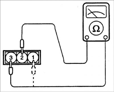
Checking the sensor
1. Measure the voltage between pins 1 and 3 of the sensor connector.
Temperature | Output voltage |
0°C | 3.3-3.7 V |
20°C | 2.4-2.8 V |
40°C | 1.6–2.0 V |
80°C | 0.5–0.9 V |
2. If the sensor output voltage is different from the required value, replace the sensor.
Manifold Absolute Pressure Sensor, Except "OBD" (MAF – Manifold Absolute Pressure)

The manifold absolute pressure sensor is a sensitive variable resistor. It measures the pressure in the intake manifold, which changes depending on the engine operating conditions and is converted into voltage. The sensor is also used to measure atmospheric pressure when starting the engine and provides engine operating conditions at different altitudes above sea level. Based on the information from the sensor, the engine control unit regulates the amount of fuel supplied to the engine and changes the ignition timing.
Examination
1. Measure the voltage between pins 1 and 4 of the sensor connector.
- Output voltage with ignition on and engine not running: 4–5 V
- Output voltage at idle frequency: 0.5-2.0 V
2. If the sensor output voltage is different from the required value, replace the sensor.
Engine Air Intake Temperature Sensor (IAT – intake air temperature)
The engine air temperature sensor is a thermistor whose resistance changes depending on temperature. The ECM takes the sensor signal into account and adjusts the pulse width supplied to the injectors, which changes the amount of fuel supplied to the engine cylinders and changes the ignition timing.
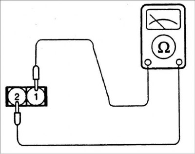
Examination
1. Measure the resistance between pins 1 and 2 of the sensor connector.
Temperature | Resistance |
0°C | 4.5–7.5 Ohm |
20°C | 2.0–3.0 Ohm |
40°C | 0.7–1.6 Ohm |
80°C | 0.2–0.4 Ohm |
2. If the sensor resistance differs from the required value, replace the sensor.
Coolant temperature sensor (ECT – Engine Coolant temperature)
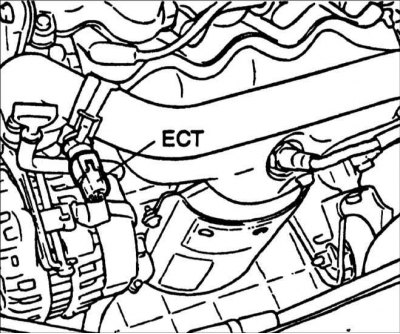
The coolant temperature sensor monitors the coolant temperature and, based on the sensor signal, the ECM calculates the pulse width supplied to the injectors, which changes the amount of fuel supplied to the engine cylinders and also changes the ignition timing.
When the engine is cold, the ECM operates in an open loop mode, which results in a richer air/fuel mixture being supplied to the engine cylinders and an increased idle speed. This continues until the engine reaches normal operating temperature.
Removal
1. Remove the sensor from the engine.
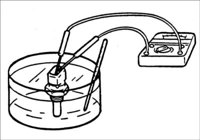
2. By heating a vessel with water and a sensor located in it, check its resistance.
Temperature | Resistance |
–30°C | 22.22–31.78 kOhm |
–10°C | 8.16–10.74 kOhm |
0°C | 5.18–6.60 kOhm |
20°C | 2.27–2.73 kOhm |
60°C | 1.059–1.281 kOhm |
40°C | 0.538–0.650 kOhm |
80°C | 0.298–0.322 kOhm |
90°C | 0.219–0.243 kOhm |
3. If the sensor resistance differs from the required value, replace the sensor.
Installation
1. Apply LOCTITE 962T sealant to the sensor threads.
2. Screw the sensor into the cylinder block and tighten it to the specified torque.
Tightening torque: 15–20 Nm
3. Connect the electrical connector to the sensor.
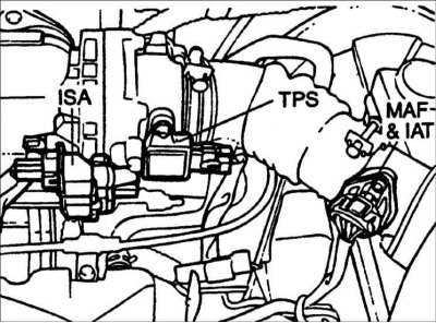
Throttle position sensor (TP – Throttle Position)
The throttle position sensor provides information to the ECM to determine when the throttle valve is closed, fully open, or in between. The sensor is rigidly connected to the throttle shaft. Depending on the position of the throttle valve, the resistance of the sensor changes. To power the sensor, the ECM supplies 5 V. The sensor's output voltage varies from 0.25 V at minimum throttle opening to 4.7 V at full throttle opening.
Examination
1. Disconnect the connector from the throttle position sensor.
2. Measure the resistance between pins 1 and 2 of the sensor connector.
Resistance: 0.7–3.0 kOhm
3. Connect an ohmmeter to pins 1 and 3 of the sensor connector.
4. Slowly open the throttle valve and check that the sensor resistance changes smoothly in proportion to the throttle valve opening.
5. If the sensor resistance differs from the required value or changes abruptly, replace the sensor.
Tightening torque: 1.5–2.5 Nm
Camshaft Position Sensor (CMP – Camshaft Position Sensor)
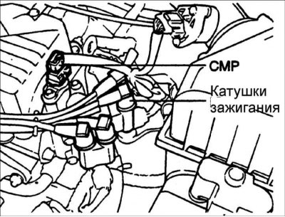
The camshaft position sensor generates pulses that the ECM uses to identify the first cylinder and the injector opening time.
Crankshaft angle sensor (CKP – Crankshaft Position Sensor)

The crankshaft angle sensor provides the ECM with information about the position of the crankshaft. Based on the output signal from this sensor and the signal from the camshaft position sensor, the ECM determines the ignition timing and the cylinder to which fuel should be supplied. Without the sensor output signals, the engine will not start.
Examination
1. Disconnect the connector from the crankshaft angle sensor
2. Measure the resistance between pins 1 and 2 of the sensor connector.
Resistance: 0.486–0.594 kOhm at 20°C
3. If the sensor resistance differs from the required value, replace the sensor.
- Gap between rotor and crankshaft angle sensor: 0.5–1.0 mm
- Tightening torque: 9–11 Nm
Oxygen sensor
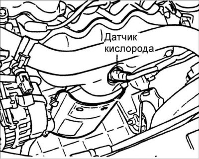
Depending on the oxygen content in the exhaust gases, the oxygen sensor induces a voltage of 0 to 1 V. Based on this data, the engine control unit changes the injector opening time and the fuel ratio in the fuel-air mixture. In order for the combustible mixture to burn completely and the exhaust gases to be free of harmful substances, there must be 1 part fuel per 14.7 parts by weight of air.
The oxygen sensor is equipped with a heater that maintains the sensor temperature within a certain range when the engine is running in all operating modes. Maintaining a certain sensor temperature allows the system to start up faster and operate in idle mode.
Examination
Warning: Before checking, warm up the engine until the coolant temperature is 80–95°C.
Warning: Use an accurate digital voltmeter to measure the sensor output voltage.
If the sensor output voltage is different from the required value, replace the sensor.
Tightening torque: 50–60 Nm
Fuel injectors
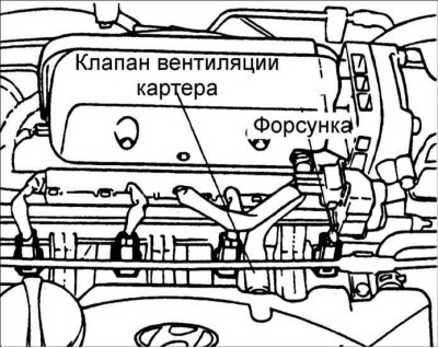
Fuel injectors inject fuel into the engine cylinders based on signals from the ECM. The amount of fuel supplied depends on the injector opening time, i.e. on the width of the voltage pulse supplied to the injector winding.
Examination
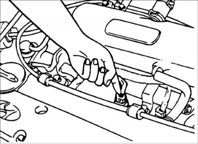
1. With the engine idling, use a stethoscope or your finger to check the operation of the injectors for clicks.
2. If there are no clicks, check the reliability of the connection of the connectors to the injectors and the output voltage of the control unit.
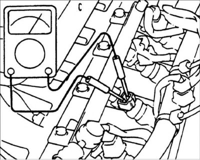
3. Disconnect the connector from the fuel injector and measure the resistance between the connector terminals.
Resistance: 15.9±0.35 Ohm
4. Connect the connector to the fuel injector.
Knock sensor
The knock sensor reacts to high-frequency vibrations of the cylinder block and converts them into electrical signals, the magnitude of which increases with increasing detonation. Based on these signals, the ECM shifts the ignition timing towards delay, as a result of which detonation is eliminated.
Fuel lines and hoses
Fuel lines and hoses provide fuel transfer from the fuel tank to the fuel rail and injectors and return excess fuel to the tank. Fuel lines attached to the underbody of the vehicle should be periodically inspected for dents and deformation, as narrowing of their passages may restrict fuel flow.
Fuel lines and hoses also provide the transfer of fuel vapors from the fuel tank to the activated carbon canister, where they are collected when the engine is turned off. Once the engine is started and warmed up to operating temperature, the engine control unit opens the solenoid valve, and fuel vapors from the canister enter the engine and are burned.