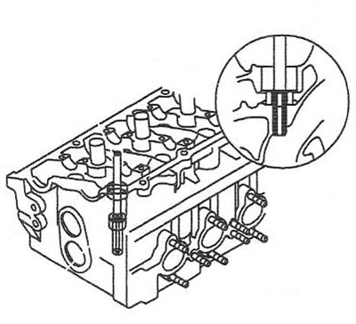
Block head
1. Using a metal ruler and a set of flat feeler gauges, check the flatness of the surface of the head of the block Limit value: 0.05 mm (from the gasket side); 0.03mm (from the collector side).
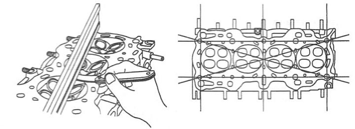
2. Check combustion chambers, inlet and outlet ports and cylinder bore for cracks. If damage is found, replace the block head.
Valve guides
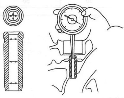
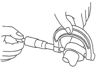
3. Using a bore gauge, measure the inside diameter of the valve guide in several places along mutually perpendicular diameters. Nominal value: 6.500-6.015 mm.
4. Using a micrometer, measure the diameter of the valve stem in several places along mutually perpendicular diameters. Rated value: 5.955-5.970 mm (inlet valve); 5.935-5.950 mm (Exhaust valve).
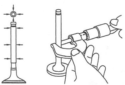
5. Calculate the clearance between the valve stem and guide sleeve. Rated value: 0.03-0.06mm (inlet valve); 0.05-0.08mm (Exhaust valve). If the value obtained is greater than the nominal value, replace the valve and bushing.
Guide bush replacement
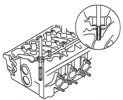
6. Using a suitable mandrel, press the guide bush out of the block head.
7. Ream the mounting holes of the block head in accordance with the repair dimensions of the bushings (see table).
8. Using a suitable mandrel, press in the guide bush. The sleeve should be pressed in from the top side of the block head.
Attention: the inlet and exhaust valve bushings have different lengths:
- 36.3-36.7 mm (inlet valve);
- 40.8-41.2mm (Exhaust valve).
Repair dimensions of valve guides
| Size, mm | Size designation | Sleeve bore diameter, mm | Sleeve outer diameter, mm |
| Nominal | - | 11,000-11,018 | 11,050-11,060 |
| +0,05 | 5 | 11,050-11,068 | 11,100-11,110 |
| +0,25 | 25 | 11,250-11,268 | 11,300-11,310 |
| +0,50 | 50 | 11,500-11,518 | 11,550-11,560 |
| +0,50 | 50 | 11,500-11,518 | 11,550-11,560 |
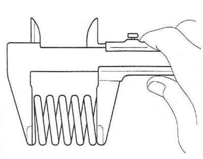
 |  Nominal value: Nominal value:
1.1-0.8mm (inlet valve) 1.3-1.0mm (Exhaust valve) |
9. After installing the bushings, insert the new valves and check the clearance between the bushing and the valve stem with a travel indicator by shaking the valve stem.
10. Check for correct seating of the valve. If necessary, refinish the sealing surfaces of the valve seats.
Valves
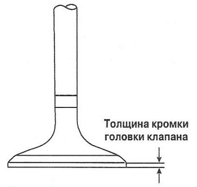
11. Check valve head bevel angle and excessive wear. Replace valves if damage is found.
12. Check valve head lip thickness. Rated value: 1.1-0.8mm (inlet valve); 1.3-1.0mm (Exhaust valve). If the measured value is less than the nominal value, replace the valve.
13. Check the valve stem for damage. If defects are found, replace the valve.
Valve seats
14. Check valve seats for wear and burns. Rework or replace valve seats as needed. Before reworking seats, check for wear on the guide bushing. If the bushing is excessively worn, replace it and grind the valve seats to repair dimensions.
 |  |
15. After repairing the seat, lap the valve with lapping paste. Make sure that the contact strip of the valve with the seat is located in the middle of the chamfer of the valve disc.
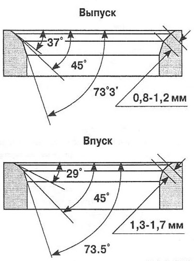
Valve seat replacement
16. Remove as much metal from the seats as possible, being careful not to damage the block head.
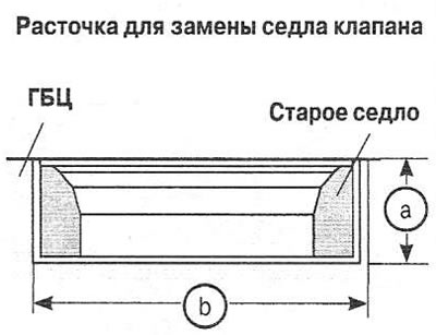 a. Boring depth for a new seat = +0.30-0.60 mm a. Boring depth for a new seat = +0.30-0.60 mm
V. Boring diameter for a new seat = + 0.30-0.60 mm | 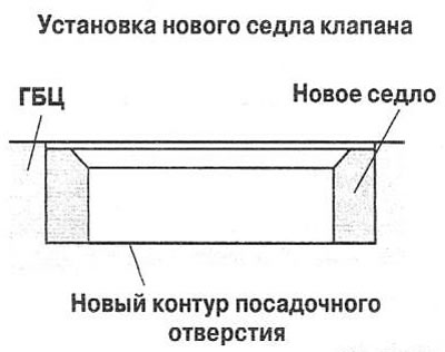 |
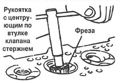
17. Increase the diameter of the valve seat seats to match the oversize of the valve seat.
18. Heat the block head to 250°C and press in the valve seats.
19. Lap the valves to the seat with lapping paste.
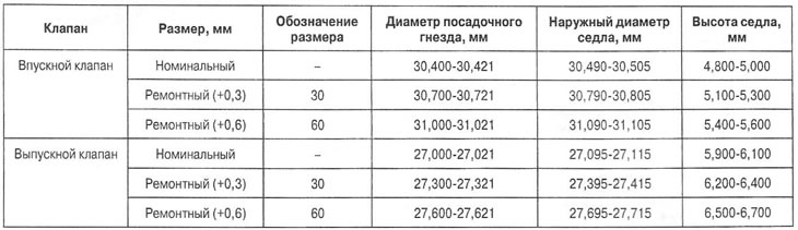
Repair dimensions of valve seats
Valve springs
20. Using a square, check the deflection of the valve spring from the vertical. Rated value: less than 1.5°.
21. Use a caliper to measure the free height of the spring. Nominal value: 44.0 mm.
22. Check the height of the valve spring under load 216±11 and 451±22 N. Nominal value: 35.0 and 27.2 mm, respectively. If the nominal value is not reached, replace the spring.
Camshaft
23. With a micrometer, measure the height of the camshaft cams. Rated value: intake camshaft - 43.3484-43.5484 mm; exhaust camshaft - 43.7489-43.9489 mm (1.4 l), 43.5486-43.7486 mm (1.6 l). If the measured value is less than the nominal value, replace the camshaft.
Bearing clearance check
24. Clean the bearing caps and camshaft journals.
25. Install the camshafts on the block head.
26. Place a piece of plastic gauge on each camshaft journal.
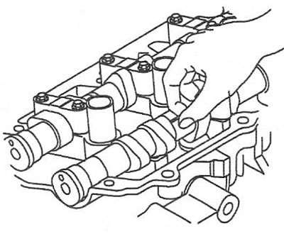
27. Install the bearing caps and torque tighten the mounting bolts.
Attention: do not rotate the camshaft.
28. Remove the camshaft bearing caps.
29. Using the control scale, measure the width of the flattened section of the gauge at its widest point. Nominal clearance: 0.020-0.061 mm. Limit clearance: 0.1 mm. If the clearance exceeds the maximum value, replace the camshaft or cylinder head.
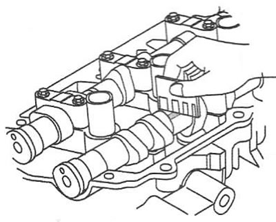
30. Completely remove the plastic gauge.
Axial clearance check
31. Install the camshaft and bearing caps.
32. Use an indicator to measure the axial clearance of the camshaft by moving it back and forth with a screwdriver. Nominal value: 0.056-0.064 mm. If the gap exceeds the nominal value, replace the camshaft or cylinder head.
33. Remove camshafts.
Timing phase regulator
34. Make sure the timing adjuster does not turn.
35. Seal with adhesive tape all channels except for the hole indicated by the arrow.
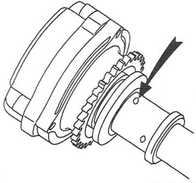
36. Apply air at a pressure of approximately 98 kPa to the free opening of the camshaft to unlock the lock pin in the maximum retard position.
Note: Place a clean rag around the hole to prevent oil from splattering. If the air pressure is insufficient, the lock pin will not unlock.
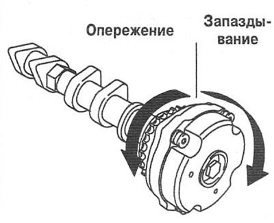
37. Keeping the pressure constant, turn the regulator forward.
38. Stop supplying compressed air to the duct.
39. Turn the regulator from side to side several times, without bringing it to the position of the maximum delay, and check the smoothness of rotation. Adjustment range: approx. 20°.
40. Manually turn the regulator to the maximum retard position and lock it.
Hydraulic pushers
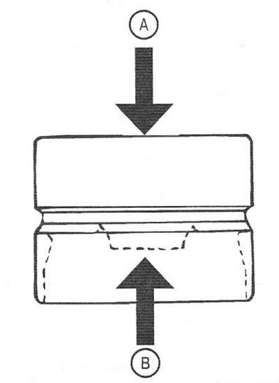
41. Holding the top side (A), press the membrane with your finger (IN) fully oil-filled hydraulic tappet. If the diaphragm moves, replace the plunger.
Possible malfunctions of the hydraulic pusher