


Contents: Checking the clearance in the…⇓ Connecting rod marking ⇓ Marking of crankshaft connecting rod…⇓ Connecting rod bearing marking ⇓ Table for selection of connecting…⇓
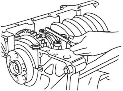
1. Using a set of flat feeler gauges, measure the axial runout of the connecting rod by moving it back and forth. Nominal value: 0.1-0.25 mm. Limit value: 0.4 mm.
2. Before installation, check that the cylinder numbers on the connecting rod and cover match. When installing a new connecting rod, make sure that the grooves for holding the bearing shells are located on the same side.
3. Check the working surfaces of the connecting rod. If any mechanical damage or wear of the upper head is detected, replace the connecting rod.
4. Using a special device, measure the amount of bending and twisting of the connecting rod. The maximum permissible value: bending - 0.05 mm per 100 mm of length; twisting - 0.1 mm per 100 mm of length. If the measurement result differs slightly from the limit value, straighten the connecting rod using a press. If the values differ significantly, the connecting rod must be replaced.
Checking the clearance in the connecting rod bearing
5. Check that the marks on the connecting rod and cover match.
6. Unscrew the 2 nuts securing the connecting rod bearing cap.
7. Remove the connecting rod bearing cap and lower bearing shell.
8. Clean the connecting rod bearing and crankshaft journal.
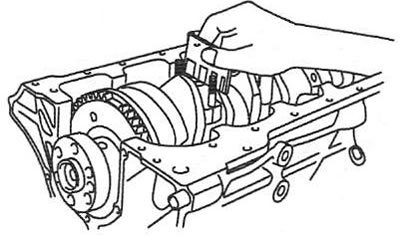
9. Place a piece of plastic gauge on the crankshaft journal.
10. Install the connecting rod bearing cap and tighten the mounting nuts to the specified torque.
Note: Do not turn the crankshaft.
11. Remove the cover and lower bearing shell.
12. Using a control scale, measure the width of the flattened section of the gauge at its widest point. Nominal clearance: 0.018-0.038 mm. If the clearance exceeds the maximum permissible value, replace the connecting rod bearing with a new one with the same marking and repeat the check.
Caution: Mechanical processing of the inserts or cover is not permitted.
13. If the clearance in the new bearings still does not correspond to the required value, select a larger or smaller bearing shell (in accordance with the marking) and repeat the check.
Note: If the required clearance value is not achieved by selecting liners, replace the crankshaft.
Connecting rod marking
| Label | Inner diameter, mm |
| a | 48,000-48,006 |
| ь | 48,006-48,012 |
| with | 48,012-48,018 |
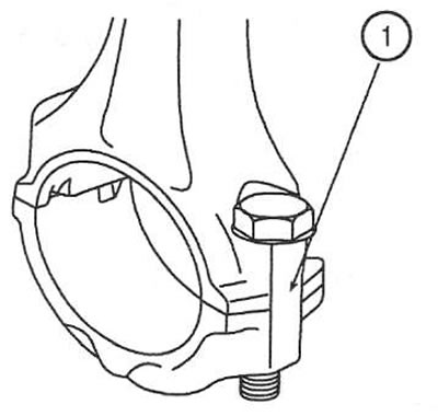
1. Mark of the size group of the connecting rod bearing seat hole
Marking of crankshaft connecting rod journals
| Label | Neck diameter, mm |
| a | 44,966-44,972 |
| b | 44,960-44,966 |
| with | 44,954-44,960 |
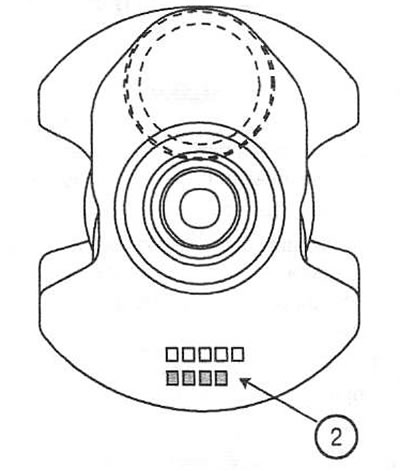
2. Letter marking of the size group of connecting rod journals
Connecting rod bearing marking
| Class | Marking | Insert thickness, mm |
| AA | Blue | 1,514-1,517 |
| A | Black | 1,511-1,514 |
| IN | - | 1,508-1,511 |
| WITH | Green | 1,505-1,508 |
| D | Yellow | 1,502-1,505 |
(This article is based on information from the website: www.HyundaiBook.ru)
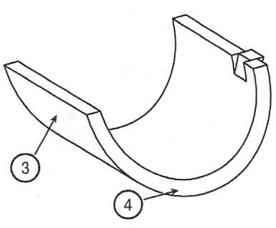
3. Letter marking of the insert
4. Color mark
Table for selection of connecting rod bearing liners
