


Contents: Composition of the crank mechanism ⇓ Composition of the connecting rod…⇓ Disassembly ⇓ Assembly ⇓
Composition of the crank mechanism
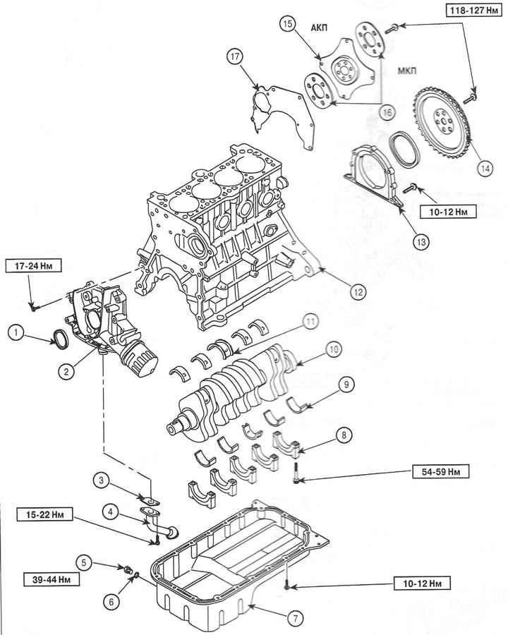
1. Seal
2. Front crankcase cover
3. Gasket
4. Oil receiver
5. Drain plug
6. Sealing ring
7. Oil pan
8. Root cap
9. Main bearing
10. Crankshaft
11. Thrust bearing
12. Cylinder block
13. Rear oil seal housing
14. Flywheel
15. Torque converter drive plate
16. Washer
17. Back plate
Composition of the connecting rod and piston group
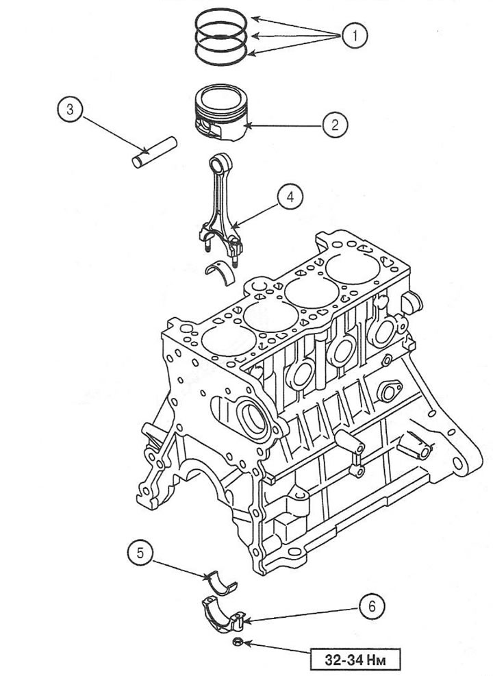
1. Piston rings
2. Piston
3. Piston pin
4. Connecting rod
5. Connecting rod bearing shell
6. Connecting rod bearing cap
Disassembly
1. Remove the flywheel (manual transmission) or torque converter drive plate (automatic transmission). Tightening torque: 117-127 Nm.
2. Install the engine on the workbench.
3. Remove the timing belt.
4. Remove the cylinder head.
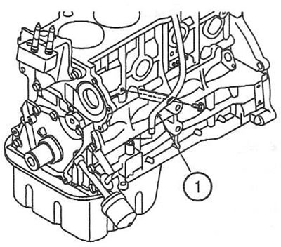
5. Remove the oil dipstick tube (1). Tightening torque: 12-15Nm.
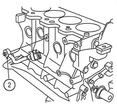
6. Remove the knock sensor (2). Tightening torque: 17-27 Nm.
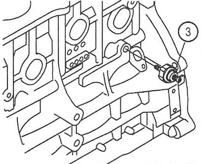
7. Remove the oil pressure sensor (3). Tightening torque: 15-22 Nm.
Note: When installing, apply MS 721-39 or TB 2310/2350 sealant to 2-3 threads of the sensor.
8. Remove the coolant pump.
9. Remove the oil pan.
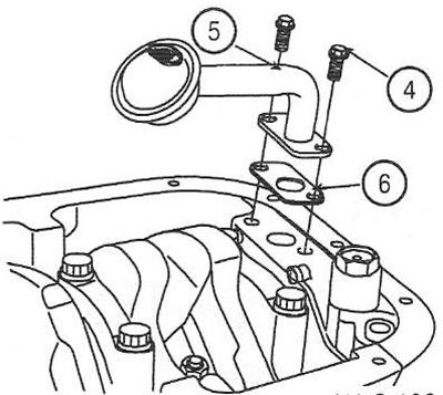
10. Unscrew 2 screws (4) and remove the oil receiver (5) with the gasket (6). Tightening torque: 15-22 Nm.
11. Check the connecting rod side clearance.
12. Check the clearance in the connecting rod bearings.
13. Remove carbon deposits from the top of the cylinder. Push the piston assembly with the connecting rod and upper connecting rod bearing shell out through the top of the cylinder.
Note: Keep the connecting rod and connecting rod bearing cap together for proper assembly later.
14. Remove the front cylinder block cover.
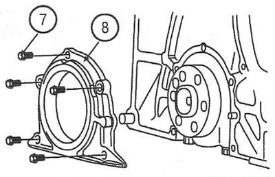
15. Unscrew 5 screws (7) and remove the crankshaft rear oil seal housing (8).
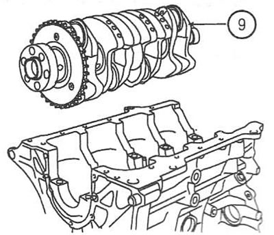
16. Carefully remove the crankshaft (9) from the cylinder block.
Note: Keep the main bearing shells in the order they were removed.
17. Try moving the piston back and forth on the piston pin. If there is even a slight gap, replace the piston and piston pin.
18. Using a puller, remove both compression rings. Remove the discs and the oil ring expander by hand
19. Using a press, press out the piston pin and remove the piston from the connecting rod.
Assembly
Note: Before assembly, thoroughly wash all parts and apply clean engine oil to the working surfaces of the parts. Replace all gaskets, seals and rings.
20. Using a press, assemble the piston with the connecting rod. Make sure that the marks on the connecting rod and piston are facing the timing belt.
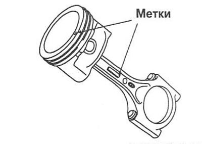
21. Install the oil ring expander and two discs by hand. Using a suitable tool, install the compression rings with the marks facing up.
22. Position the piston ring locks as shown.
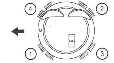
- 1. 1st compression ring
- 2. 2nd compression ring
- 3. Upper part of the oil scraper ring
- 4. Lower part of the oil scraper ring
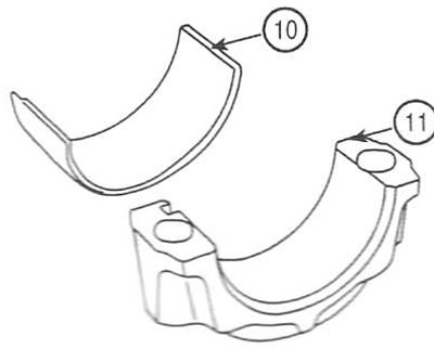
23. Align the protrusion of the bearing shells (10) with the grooves in the connecting rod cover (11) and install the bearing shells.
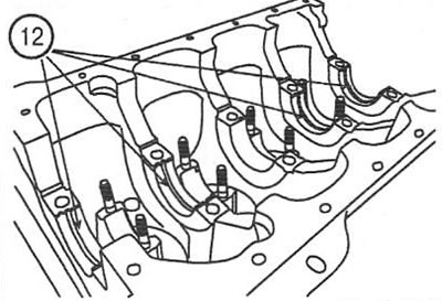
24. Install the upper crankshaft main bearing shells (12) (do not install the center main bearing shell), aligning the protrusions on the shells with the recesses on the cylinder block.
Note: The upper main bearing shells have a grease
25. Install the lower crankshaft main bearing shells, aligning the protrusions on the shells with the recesses on the covers.
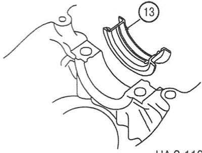
26. Install the upper shell (13) of the central main bearing No.3.
27. Install the crankshaft into the cylinder block.
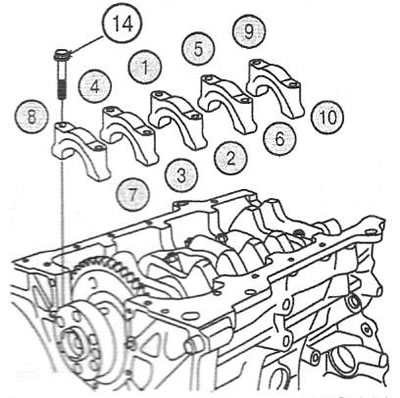
28. Install the main bearing caps.
29. Using a torque wrench, tighten the main bearing cap screws (14) in the specified sequence in 2 stages. Tightening torque: 54-69 Nm.
Note: Apply clean engine oil to the threads and under the heads before installing the screws.
30. Check the ease of rotation of the crankshaft
31. Check the axial run-out of the crankshaft.
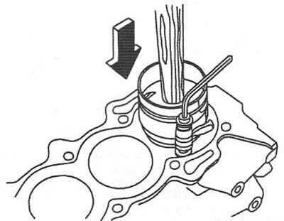
Note: Before installing the pistons, apply a thin layer of engine oil to the piston rings and cylinder walls.
32. Install the piston ring compressor, position it on the cylinder block and install the piston into the cylinder by tapping it lightly with the wooden handle of the hammer. Once the compressor is released, check the alignment of the connecting rod with the crankshaft and push the piston fully into the cylinder.
33. Apply engine oil to the bolt threads and tighten the connecting rod cap nuts. Tightening torque: 32-34 Nm.
34. Check the axial run-out of the connecting rods.
Note: Clean the surfaces of the rear oil seal housing and cylinder block. Remove all foreign particles from the surface before applying the sealant.
35. Apply MS 721-40A or Loctite 5900 sealant to the surface of the rear oil seal housing between the outer and inner faces. The sealant layer should be on the inside of the screw holes.
Note: Install the oil seal housing within 5 minutes after applying the sealant.
36. Install the oil seal housing and tighten the 5 mounting screws. Tightening torque: 10-12 Nm.
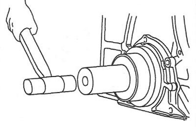
Note: Apply engine oil to the seal lips before installation.
37. Using a suitable drift, install the rear oil seal into the housing.
38. Further assembly is carried out in reverse order.