Contents: Checking the clearance in the main…⇓ Crankshaft bearing markings ⇓ Marking of crankshaft main journals ⇓ Main bearing marking ⇓ Table for selection of main bearing…⇓ Checking the axial run-out of the…⇓ Checking geometric parameters ⇓
Checking the clearance in the main bearing
1. Remove the main bearing cap and lower shell.
2. Clean the bearing and crankshaft journal.
3. Place a piece of plastic gauge on each crankshaft main journal.
4. Install the bearing caps and tighten the mounting screws. Tightening torque: 54-59 Nm.
Note: Do not turn the crankshaft.
5. Remove the cover and lower bearing shell.
6. Using the control scale, measure the width of the flattened section of the gauge at its widest point. Nominal clearance: 0.022-0.040 mm.
7. If the clearance exceeds the maximum permissible value, replace the main bearing shell with a new one with the same marking and repeat the check.
(The article is borrowed from an online resource: www.HyundaiBook.ru)
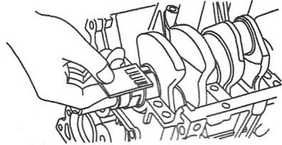
Caution: Mechanical processing of the inserts or cover is not permitted.
8. If the clearance in the new bearings still does not correspond to the required value, select a larger or smaller bearing shell (in accordance with the marking) and repeat the check.
Note: If the required clearance value is not achieved by selecting bearings, replace the crankshaft.
Crankshaft bearing markings
Note: The letter markings for all five crankshaft bearings are stamped on the bottom of the cylinder block.
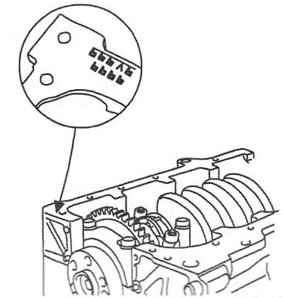
| Label | Inner diameter, mm |
| a | 54,000-54,006 |
| b | 54,006-54,012 |
| with | 54,012-54,018 |
Marking of crankshaft main journals
| Label | Neck diameter, mm |
| a | 49,962-49,968 |
| b | 49,956-49,962 |
| with | 49,950-49,956 |
Note: All five crankshaft main journal markings are stamped on the front crankshaft balancer.
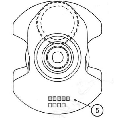
5. Letter marking of the size group of main journals
Main bearing marking
| Class | Color coding | Insert thickness, mm | |
| №1,2,4,5 | №3 | ||
| AA | Blue | 2,014-2,017 | 2,011-2,014 |
| A | Black | 2,011-2,014 | 2,008-2,011 |
| IN | - | 2,008-2,011 | 2,005-2,008 |
| WITH | Green | 2,005-2,008 | 2,002-2,005 |
| D | Yellow | 2,002-2,005 | 1,999-2,002 |
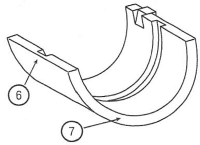
6. Letter marking of the insert
7. Color mark
Table for selection of main bearing shells

Checking the axial run-out of the crankshaft
9. Use an indicator to measure the axial runout of the crankshaft by moving it back and forth with a screwdriver. Nominal value: 0.05-0.175 mm. Limit value: 0.2 mm.
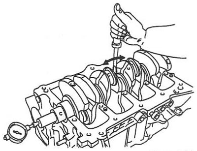
10. If the measured value is greater than the maximum allowable value, replace the thrust bearing.
Checking geometric parameters
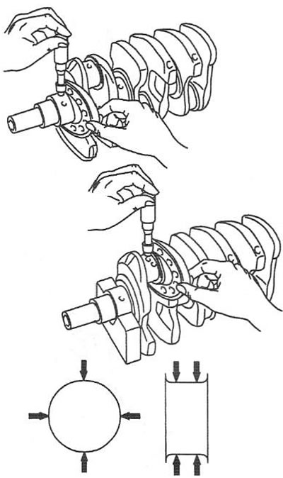
11. Using a micrometer, measure the diameter of all main and connecting rod journals. Nominal value: 49.950-49.968 mm (main journal); 44.954-44.972 mm (crank pin).