
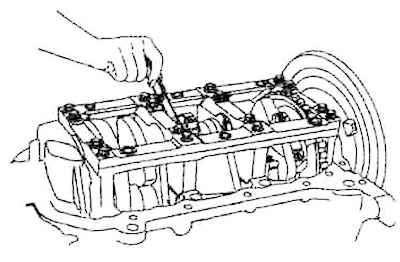
2. The clearance between the liners and the shaft journals can be checked using a calibrated plastic wire. To do this, clean the shaft journals and liners from oil, grease and other contaminants. Place pieces of calibrated plastic wire of a length equal to the width of the liner on the journals so that the wire does not block the lubrication holes. Install the crankshaft, liners and bearing caps. Tighten the cap mounting bolts to the required torque, making sure that the shaft does not turn. Remove the bearing caps. Determine the clearances between the bearing liners and the shaft journals by the width of the most flattened section of the wire using the scale on the wire packaging. If the clearances exceed the maximum permissible value, replace the bearing liners. If replacing the liners does not produce normal clearances, grind the crankshaft journals to the repair size and install liners of the corresponding repair size.
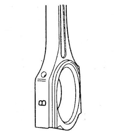
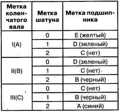
3. Select the repair size of the connecting rod and piston group according to the marks on the parts:

1) Position of the connecting rod mark.
 |
 |
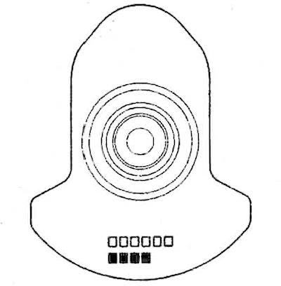
2) Position of the crankshaft mark.
 |
 |
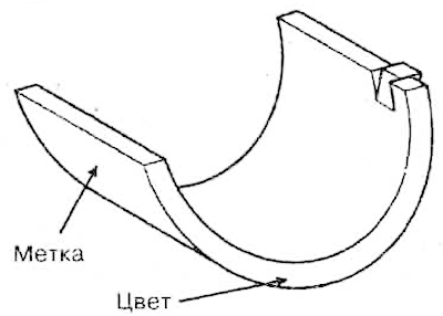
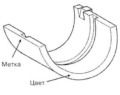
3) Position of the mark on the connecting rod bearing.
 |
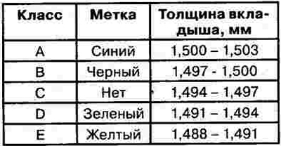 |
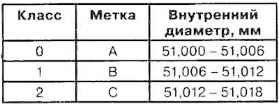
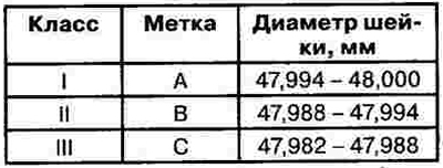
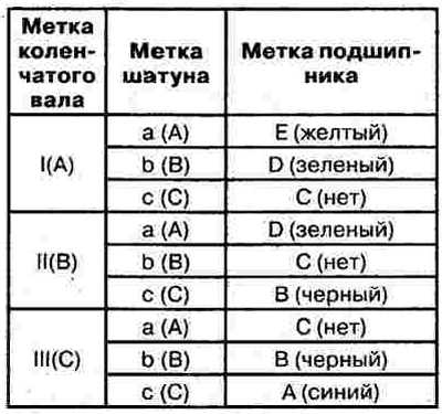
4) The selection of parts according to the group of repair dimensions is carried out according to the table.
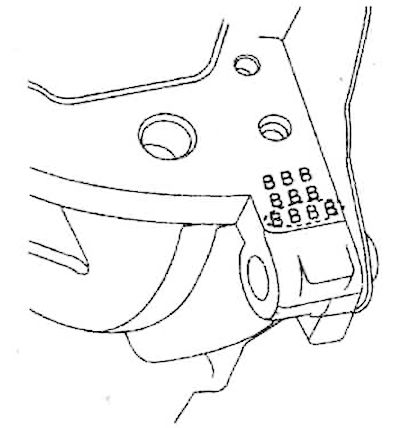
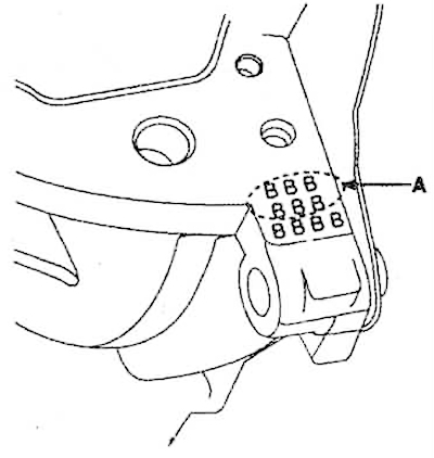
4. The letters stamped on the end of the cylinder block are the size mark for each of the four main bearings. Use these marks, as well as the marks on the crankshaft, to select the connecting rod bearings. The position of the marks for selecting the main bearing shells:
1) Position of marks on the cylinder block.
 |
 |
2) Position of marks on the crankshaft.
 |
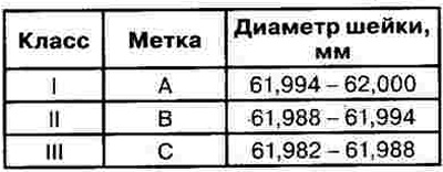 |
3) Position of marks on the main bearing shell.
 |
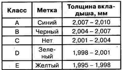 |
4) The selection of parts according to the group of repair dimensions is carried out according to the table.
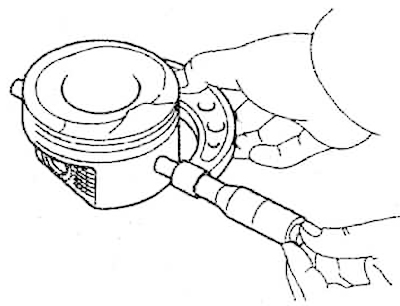
5. If connecting rods are re-installed during assembly, ensure that they are installed in the same cylinders in which they were located before disassembly. If new connecting rods are installed, ensure that the connecting rod mark is on the same side as the bearing lock. Replace the connecting rod if any visible damage is found or excessive connecting rod wear is evident.
6. Using a special device, check the connecting rods for bending or twisting. Permissible bending of the connecting rod: 0.05 mm per 100 mm of length or less. Permissible twisting: 0.1 mm per 100 mm or less. If the bending or twisting of the connecting rod is close to the permissible value, but still exceeds it, it is permissible to straighten the connecting rod with a press. If there is excessive bending or twisting, the connecting rod must be replaced with a new one.
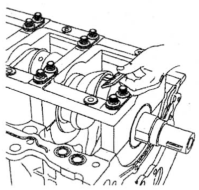
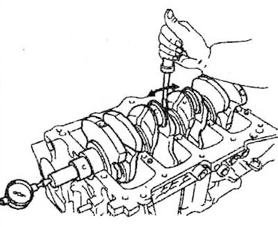
7. Using a dial indicator, check the crankshaft axial clearance by moving it along the cylinder block with a screwdriver. Nominal axial clearance: 0.07 - 0.25 mm. Maximum permissible axial clearance: 0.30 mm. If the axial clearance exceeds the maximum permissible, replace the thrust bearings as a set. Thrust bearing thickness: 2.05 - 2.09 mm.
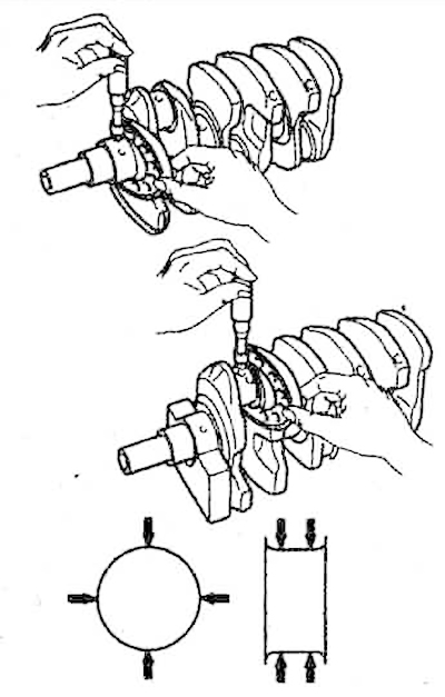
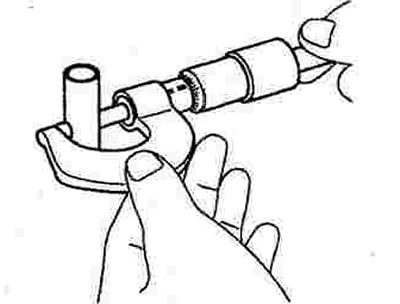
8. Using a micrometer, measure the diameter of each main and connecting rod journal of the crankshaft at the locations indicated by arrows in the figure. Nominal diameter of main journals: 61.982 - 62.000 mm. Nominal diameter of connecting rod journals: 47.982 - 48.00 mm.
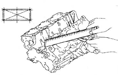
9. Use a scraper to remove the gasket residue from the cylinder block surface, then use a brush and solvent to thoroughly clean the entire cylinder block. Using a ruler and feeler gauge, check the non-flatness of the cylinder block contact surface at the locations shown in the figure. The standard value of non-flatness of the contact surface: less than 0.03 mm. The maximum permissible non-flatness of the surface: 0.05 mm.
10. Inspect the cylinder bore for scratches. If there are deep scratches, the cylinder liner must be replaced or bored.
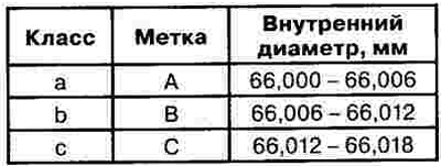
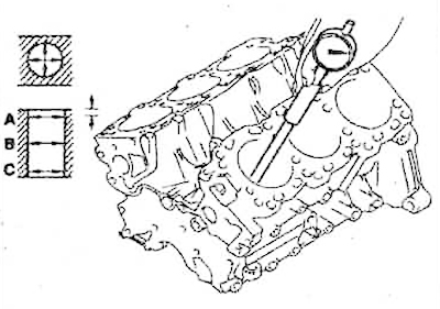
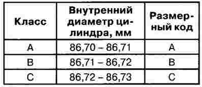
11. Using a bore gauge, measure the cylinder diameter at points A, B and C in mutually perpendicular planes. Nominal cylinder diameter: 86.70 -86.73 mm.
12. Check the cylinder diameter marks (A) on the cylinder block surface.
 |
 |
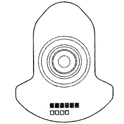
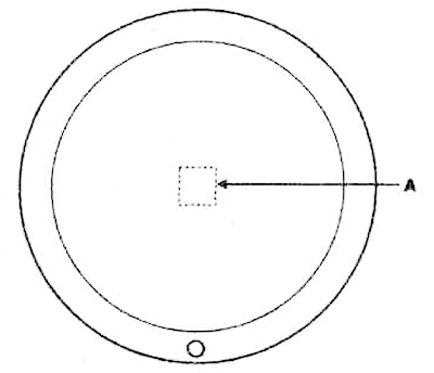
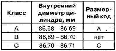
13. Check the piston size code (A) on its upper surface.
 |
 |
14. Select the piston according to the repair size of the cylinder liner. In this case, take into account that the gap between the piston and the cylinder: 0.01 - 0.03 mm.
15. In case of severe wear of the cylinder liner, pistons of increased size should be selected according to the largest diameter of the cylinder liner hole. The repair sizes of pistons are increased by 0.25 and 0.5 mm, the corresponding marks are applied to the upper part of the piston.
16. Measure the piston diameter and calculate the new cylinder diameter:
New cylinder diameter = piston diameter + (0.01 - 0.03 mm, clearance between piston and cylinder) - 0.01 mm (honing tolerance).
17. Bore each cylinder to the calculated diameter, then hone.
18. Check the clearance between the piston and the valve. It should be within 0.01-0.03 mm.
Note: When boring at least one cylinder, bore all other cylinders to the same repair size.
19. Measure the main diameter of the piston (39 mm from the bottom) with a micrometer. Nominal piston diameter: 86.68 -86.71 mm. If the piston is heavily worn, it must be replaced with a new one.
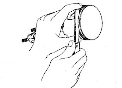
20. Use a feeler gauge to measure the gap between the new piston ring and the piston groove.
The lateral clearance should be:
- Piston ring No.1: 0.04 - 0.08 mm;
- Piston ring No.2: 0.03 - 0.07 mm.
The maximum permissible value of the lateral clearance is 0.1 mm for both piston rings.
If the side clearance is greater than the permissible limit, replace the piston.
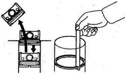
21. To check the ring gap in the lock, insert the ring into the cylinder. Set the ring at a right angle to the cylinder wall, pressing it lightly with the piston. Check the gap in the ring lock with a feeler gauge.
Gap in the lock:
- Piston ring No.1: 0.20 - 0.35 mm;
- Piston ring #2: 0.37 - 0.52 mm;
- Oil scraper ring: 0.20 - 0.70 mm.
If the gap exceeds the maximum permissible value in operation, replace the ring with a new one. When replacing rings without boring the cylinders, check the gap in the lock by installing it in the lower, less worn part of the cylinder.
22. Use a micrometer to measure the piston pin diameter. It should be 21.001-21.007 mm.
23. Measure the gap between the piston pin and the piston. It should be 0.007-0.022 mm.
24. Check the difference between the piston diameter and the hole in the upper part of the connecting rod. It should be within 0.016-0.033 mm.