


Electrical equipment and appliances Hyundai Tucson 1

General troubleshooting information
1. Check the fuses in the appropriate fuse and relay box. 2. Check the battery (charge status) and clean the contacts. 3. Check the alternator belt tension.
1. Check the fuses in the appropriate fuse and relay box. 2. Check the battery (charge status) and clean the contacts. 3. Check the alternator belt tension.

Checking electrical system connectors
1. Make sure the connectors are clean and have no damaged clamps. 2. All connectors have locks that open with a push down (A). Note: 1. On some, the lock is located on...
1. Make sure the connectors are clean and have no damaged clamps. 2. All connectors have locks that open with a push down (A). Note: 1. On some, the lock is located on...


Audio system — removal and installation
1. Disconnect the negative battery terminal. 2. Remove the gear shift cover. 3. Unscrew the three bolts. 4. Remove the audio system panel (A). 5. Unscrew the 4 mounting...
1. Disconnect the negative battery terminal. 2. Remove the gear shift cover. 3. Unscrew the three bolts. 4. Remove the audio system panel (A). 5. Unscrew the 4 mounting...


Multifunction switch — removal and installation
To remove the multifunction switch in vehicles equipped with airbags, you must follow the safety precautions for removing the airbag (see Chapter " Passive safety "). 1....
To remove the multifunction switch in vehicles equipped with airbags, you must follow the safety precautions for removing the airbag (see Chapter " Passive safety "). 1....

Sound signal — removal and installation
1. Remove the front headlights. 2. Remove the sound signals (high A, low B). Installation is carried out in the reverse order of removal.
1. Remove the front headlights. 2. Remove the sound signals (high A, low B). Installation is carried out in the reverse order of removal.

Sound signal — check
1. You can check the sound signal by connecting it to the battery. Apply (+) to the first contact and (-) to the second. 2. The signal should sound. If the signal does...
1. You can check the sound signal by connecting it to the battery. Apply (+) to the first contact and (-) to the second. 2. The signal should sound. If the signal does...

Checking the horn relay
1. Remove the relay from the relay box in the engine compartment. 2. Check the continuity of the circuit between the terminals. The circuit should be continuous between...
1. Remove the relay from the relay box in the engine compartment. 2. Check the continuity of the circuit between the terminals. The circuit should be continuous between...

Central locking and alarm — general information
The alarm system is automatically activated after the doors and hood are closed. The system is triggered under any of these conditions: One of the doors is open; The...
The alarm system is automatically activated after the doors and hood are closed. The system is triggered under any of these conditions: One of the doors is open; The...

Checking the alarm module
1. Disconnect the alarm module connector. 2. Inspect the contacts on the wire side for oxidation.
1. Disconnect the alarm module connector. 2. Inspect the contacts on the wire side for oxidation.
Central locking and alarm — technical condition check
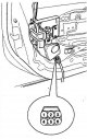
Checking the front door locks 1. Remove the door trim. 2. Disconnect the six-pin connector. 3. Check the polarity of the voltage on the contacts (it is necessary to...
Checking the front door locks 1. Remove the door trim. 2. Disconnect the six-pin connector. 3. Check the polarity of the voltage on the contacts (it is necessary to...


Testing power relays
Check the continuity of the power relay circuit. The circuit should be continuous between pin 1 and pin 2 when power and ground are connected to pin 4 and pin 3. When...
Check the continuity of the power relay circuit. The circuit should be continuous between pin 1 and pin 2 when power and ground are connected to pin 4 and pin 3. When...


Instrument panel — removal and installation
1. Disconnect the negative battery terminal. 2. Loosen 2 screws and remove the panel cover (A). 3. Loosen 4 screws, remove the instrument panel (A) and disconnect the...
1. Disconnect the negative battery terminal. 2. Loosen 2 screws and remove the panel cover (A). 3. Loosen 4 screws, remove the instrument panel (A) and disconnect the...

Instrument panel — checking the technical condition
Tachometer 1. Connect the diagnostic device. 2. Compare the readings of the diagnostic device with the readings of the tachometer. Fuel flow meter 1. Disconnect the fuel...
Tachometer 1. Connect the diagnostic device. 2. Compare the readings of the diagnostic device with the readings of the tachometer. Fuel flow meter 1. Disconnect the fuel...


Headlights — Removal and Installation
1. Disconnect the negative battery terminal. 2. Unscrew 2 bolts and disconnect the headlight connector. 3. Replace, if necessary, the headlight bulb (A - Light bulb, B -...
1. Disconnect the negative battery terminal. 2. Unscrew 2 bolts and disconnect the headlight connector. 3. Replace, if necessary, the headlight bulb (A - Light bulb, B -...

Checking the technical condition of the headlight relay
1. Remove the headlight relay (A) low beam and (B) high beam from the engine compartment relay block. 2. Apply voltage to contacts 3 and 4. Check the continuity of the...
1. Remove the headlight relay (A) low beam and (B) high beam from the engine compartment relay block. 2. Apply voltage to contacts 3 and 4. Check the continuity of the...

Turn signal lamps — removal and installation
1. Disconnect the negative battery terminal. 2. Loosen the three screws of the rear light. Disconnect the rear light connector. 3. Remove the tail light. If necessary,...
1. Disconnect the negative battery terminal. 2. Loosen the three screws of the rear light. Disconnect the rear light connector. 3. Remove the tail light. If necessary,...

Interior lighting — removal and installation
1. Disconnect the negative battery terminal. 2. Remove the lamp glass using a flat-head screwdriver. Replace the lamp if it does not work. 3. Unscrew the two screws,...
1. Disconnect the negative battery terminal. 2. Remove the lamp glass using a flat-head screwdriver. Replace the lamp if it does not work. 3. Unscrew the two screws,...

Interior lighting — checking the technical condition
Check the voltage supplied to the lamps (contacts 1 and 2). When the interior lamp is on, the voltage supplied to the connector should correspond to the battery voltage.
Check the voltage supplied to the lamps (contacts 1 and 2). When the interior lamp is on, the voltage supplied to the connector should correspond to the battery voltage.

Turn signal and hazard warning lights — checking technical condition
1. Disconnect the negative battery terminal. 2. Remove the hazard warning switch. 3. Check the continuity of the circuit between the switch contacts.
1. Disconnect the negative battery terminal. 2. Remove the hazard warning switch. 3. Check the continuity of the circuit between the switch contacts.

Lighting system circuit breaker — technical condition check
1. Remove the breaker from the interior relay block. 2. Connect the "+" from the battery to contact 2 and the "-" to contact 3. 3. Connect two turn signal lamps in...
1. Remove the breaker from the interior relay block. 2. Connect the "+" from the battery to contact 2 and the "-" to contact 3. 3. Connect two turn signal lamps in...

Front fog lights — removal and installation
1. Disconnect the negative battery terminal. 2. Disconnect the front fog light connector (A), then remove the fog light from the front bumper. 3. Installation is carried...
1. Disconnect the negative battery terminal. 2. Disconnect the front fog light connector (A), then remove the fog light from the front bumper. 3. Installation is carried...

Checking the technical condition of the front fog light relay
1. Remove relay (A) from the engine compartment relay box. 2. Apply voltage from the battery to contacts 4 and 3. Check the continuity of the circuit between contacts 1...
1. Remove relay (A) from the engine compartment relay box. 2. Apply voltage from the battery to contacts 4 and 3. Check the continuity of the circuit between contacts 1...

Fog light switch
1. Disconnect the negative terminal of the battery. 2. Remove the switch from the center panel and disconnect the connector. 3. Check the switch for continuity.
1. Disconnect the negative terminal of the battery. 2. Remove the switch from the center panel and disconnect the connector. 3. Check the switch for continuity.

Brake light bulbs — removal and installation
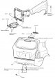
1. Disconnect the negative battery terminal. 2. Open the rear door, remove the cover (A). 3. Loosen the two nuts, disconnect the connector (B) and remove the turn signal...
1. Disconnect the negative battery terminal. 2. Open the rear door, remove the cover (A). 3. Loosen the two nuts, disconnect the connector (B) and remove the turn signal...

Automatic lighting system — device
If you set the multi-function switch to the "Auto" position, the lighting will turn on automatically.
If you set the multi-function switch to the "Auto" position, the lighting will turn on automatically.


Automatic lighting control unit — checking the technical condition
1. Remove the circuit breaker (A) from the ceiling panel. 2. Disconnect the connector (B) and remove the switch. Check the voltage at the connector.
1. Remove the circuit breaker (A) from the ceiling panel. 2. Disconnect the connector (B) and remove the switch. Check the voltage at the connector.

Adjusting the direction of the headlights
Schematic diagram of the control system switch Checking the technical condition of the switch 1. Disconnect the switch and remove it from the panel. 2. Apply battery...
Schematic diagram of the control system switch Checking the technical condition of the switch 1. Disconnect the switch and remove it from the panel. 2. Apply battery...
This section is available on russian, bulgarian, belarusian, ukrainian, serbian, croatian, romanian, polish, slovak, hungarian
We recommend other sections on the topic of Hyundai manuals:
Electrical equipment: Equipment and devices Hyundai Accent 3 (2005-2010)
Electrical equipment: Equipment and devices Hyundai Elantra 1 (1990-1995, petrol)
Electrical equipment: Equipment and devices Hyundai Getz (2002-2011)
Electrical equipment: Equipment and devices Hyundai Sonata 3 (1993-1998)
Electrical equipment: Equipment and devices Hyundai Santa Fe 2 (2007-2012, petrol)
Electrical equipment: Equipment and devices Hyundai Matrix (2001-2010, petrol)
Link in different formats to this section
TextHTMLBB Code
- General information
- Faults en route
- User manual
- Maintenance
- Power unit
- Gasoline engines
- Diesel engines
- Engine cooling system
- Engine lubrication system
- Engine power system
- Control system
- Intake and exhaust systems
- Engine electrical equipment
- Transmission
- Clutch
- Mechanical gearbox
- Automatic gearbox
- Drive shafts
- Chassis
- Suspension and wheels
- Brake system
- Steering
- Body
- Exterior (external elements)
- Interior (internal elements)
- Security systems
- Air conditioning and heater
- Electrical equipment
- Electrical circuits
- General information
- User manual
- Maintenance
- Power unit
- Gasoline engine G6BA
- Gasoline engine G4GC
- Diesel engine D4EA
- Fuel system (gasoline)
- Fuel system (diesel)
- Engine lubrication system
- Engine cooling system
- Engine electrical equipment
- Transmission
- Clutch
- Car gearbox
- Drive shafts and cardan
- Chassis
- Car suspension
- Steering
- Brake system
- Body
- Exterior (external elements)
- Interior (internal elements)
- Air conditioning and heater
- Airbags
- Electrical equipment
- Equipment and devices
- Electrical circuits