
Removal
1. To disassemble and reassemble the piston and connecting rod, use special tools 09234–33001.
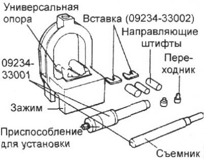
2. Install the universal supports into the clamp between the connecting rod and the piston.
3. Insert the puller through the hole in the clamp arch.
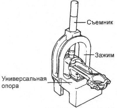
Note: Insert the clamp with the piston, connecting rod and puller under the press slide.
4. Use a puller to push the piston pin out of the piston.
Installation
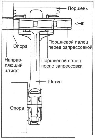
1. Install the guide pin through the piston into the connecting rod. Using light hand taps, move the guide pin so that it fits into the other piston boss. Insert the new piston pin into the piston boss on the side opposite the guide pin.
Note.
- The guide pins determine the position of the connecting rod in the piston. After the piston, connecting rod, piston pin and piston pin installation tool are installed, the guide pins also determine their position in the clamp before insertion.
- Using the wrong diameter guide pin will cause the piston to not center in the fixture, which could cause damage to the universal joint fork and/or fixture inserts.
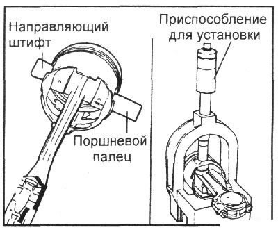
2. Install the piston assembly onto the support fork, with the guide pin supporting the connecting rod in the piston pin.
3. Adjust the length of the pressing device by rotating its numbered sleeve relative to the letter-marked rod until the alphanumeric length indicated in the operation card is obtained, then secure the numbered sleeve on the rod by rotating the knurled nut.
4. Insert the installation tool through the hole in the universal joint arch. Press the piston pin into the connecting rod until the bushing on the shaft contacts the top of the universal joint arch, causing the guide pin to fall out of the piston.
Attention! The piston pin pressing force must not exceed 22680 N.
Examination
Piston and piston pin
1. Check the outside surface of the piston for damage, wear or uneven wear. Replace the piston if necessary.
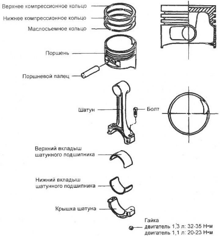
2. Check each piston ring for damage and uneven wear. Replace the piston rings if necessary. When replacing a piston, you must also replace the piston rings.
3. Check the piston pin by inserting it into the piston hole. The piston pin should enter the piston smoothly when pressed by hand (at room temperature).
Piston rings
1. Insert a new piston ring into the piston groove and use a feeler gauge to measure the gap between the piston ring and the groove wall. If the gap exceeds the maximum permissible value, replace the piston.
If the gap does not exceed the maximum permissible value, replace only the piston rings.
Clearance between piston ring and piston groove:
Upper compression ring:
- 1.3L engine: 0.04–0.085 mm
- 1.1L engine: 0.03–0.07mm
Lower compression ring:
- 1.3L engine: 0.04–0.085 mm
- 1.1L engine: 0.02–0.06 mm
Maximum permissible gap: 0.1 mm
2. Measure the piston ring gap by manually inserting the piston ring into the engine cylinder. Use the piston crown to push the piston ring into the bottom of the cylinder. Use a feeler gauge to measure the piston ring gap.
Piston ring gap:
First compression ring:
- 1.3L engine: 0.20–0.35 mm
- 1.1L engine: 0.15–0.30 mm
Second compression ring:
- 1.3L engine: 0.37–0.52 mm
- 1.1L engine: 0.30–0.50 mm
- Oil scraper ring: 0.20-0.70 mm
- Maximum clearance: 1.0 mm
When replacing rings without boring the cylinders, the gap in the lock can be checked by installing the rings in the lower, less worn part of the cylinder.
The rings must be replaced with rings of the same size group. Size groups of piston rings by gap in the lock and their marking.
Nominal: no marking 0.25 mm: 25; 0.50 mm: 50; 0.75 mm: 75; 1.0 mm: 100.
Note: Marking is located on the top surface of the ring.
Piston selection
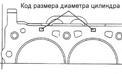
1. Check the cylinder bore size code located on the top surface of the cylinder block (1.3L engine).
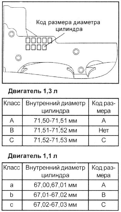
Check the cylinder bore size code located on the lower mating surface of the cylinder block (1.1L engine).
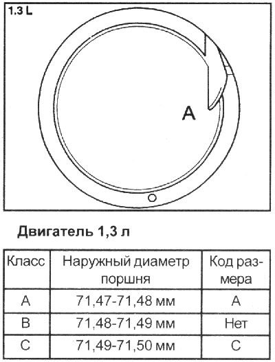
2. Check the piston diameter size code located on the piston crown.
 |
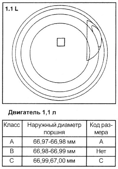 |
3. Select a piston whose diameter matches the cylinder class. The gap between the piston and the cylinder: 0.02–0.04 mm.
Installation
1. Install the oil scraper ring expander.
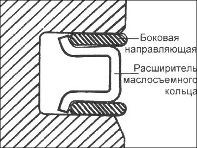
2. Install the upper side guide of the oil scraper ring. To install the side guide, first place one end of the side guide between the wall of the piston ring groove and the expansion ring, press it, and then press it into the piston groove by pressing around the perimeter.
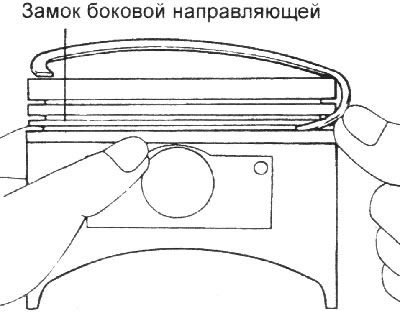
Note: Do not use pliers to spread the piston rings when installing the side guide.
3. Install the lower side guide in the same way.
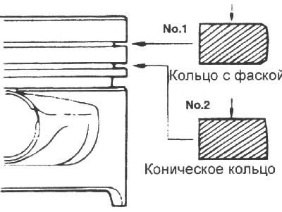
4. Using piston ring pliers, install the lower compression ring.
5. Install the upper compression ring.
6. Apply a thin layer of engine oil to the piston and piston rings.
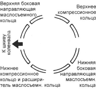
7. Position the piston ring locks as shown in the figure.
8. Using a special tool, compress the piston rings on the piston. Install the piston with the piston rings above the first cylinder. Using a hammer handle, press the piston into the cylinder so that the lower head of the connecting rod is installed on the crankshaft journal.
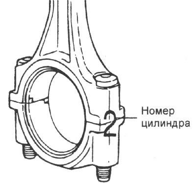
9. Make sure the marks on the pistons are facing the front of the cylinder block
10. When installing the connecting rod caps, make sure that the numbers on the connecting rods and the cap match when disassembling.
11. When installing a new connecting rod, make sure that the bearing shell recesses are on the same side.
12. Tighten the connecting rod cap bolts and nuts.
Tightening torque:
- 1.3L engines: 32–35 Nm
- 1.1L engines: 20–23 Nm
13. Using a feeler gauge inserted between the connecting rod and the crankshaft, measure the connecting rod side clearance.
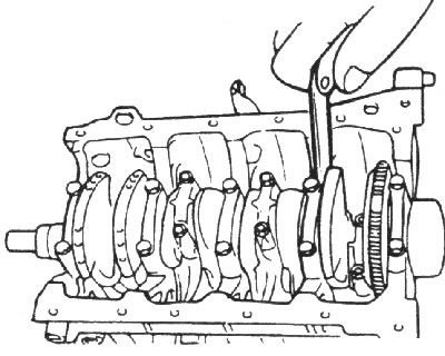
- Nominal connecting rod side clearance: 0.10 mm
- Maximum clearance: 0.40 mm