Removal
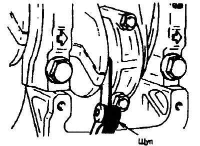
Connecting rod lower head cover
1. For subsequent installation, arrange the liners in the order corresponding to the location of the connecting rods (according to the cylinder numbers).
2. Unscrew the nut securing the lower connecting rod head caps, then remove the caps and liners.
3. Move the pistons with connecting rods to the top of the cylinders.
The procedure for removing and installing a piston ring
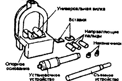
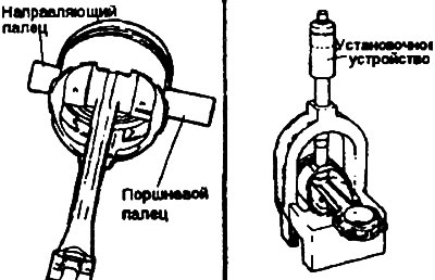
1. Using special tools (09234-33001), separate and reconnect the piston and connecting rod.
2. Install the appropriate insert into the fork of the device. Position the insert between the connecting rod and the piston.
3. Insert the appropriate removal device into the opening of the fixture arch.
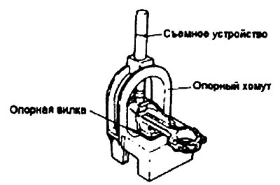
Caution: Center the piston, connecting rod, and piston pin assembly on the puller mandrel.
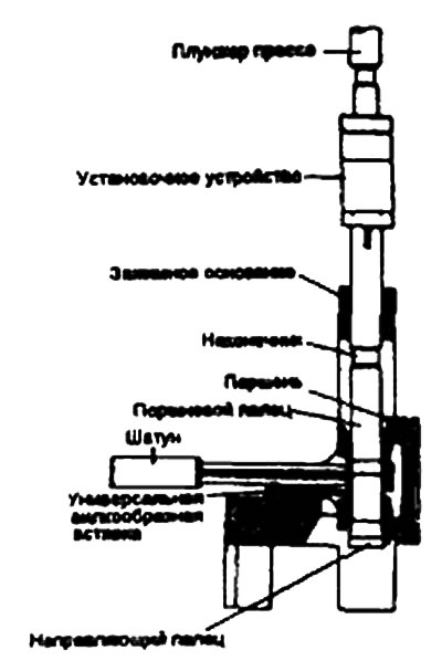
4. Press the piston pin out of the upper connecting rod head.
5. Install the appropriate guide pin into the piston and connecting rod small end. Insert the guide pin into the piston bore by hand to hold it in place. Push the piston pin out the other side of the piston.
Warning: The guide pin centers the connecting rod in the piston. When the piston, connecting rod, piston pin and guide pin are installed on the jig yoke, the guide pin centers the entire assembly in the jig. If too small a guide pin is used, the piston assembly will not be centered in the jig, which may result in damage to the jig yoke or insert.
6. Install the piston assembly onto the tool fork. The tool will support the connecting rod on the piston pin. Make sure the piston assembly slides on the fork until the guide pin contacts the insert.
7. Adjust the installation mandrel to the appropriate length by rotating the numbered sleeve on the lettered shaft until the alphanumeric value specified in the application diagram is obtained. Turn the knurled nut to lock the numbered sleeve on the shaft.
8. Insert the installation mandrel into the hole in the arc of the fixture. Press the piston pin into the connecting rod head until the bushing of the installation mandrel touches the top of the arc of the fixture.
Warning: Do not apply a load greater than 2200 kgf when pressing the mounting mandrel sleeve into the arc.
Installation
1. Install the spacer ring.
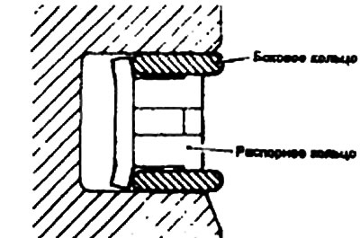
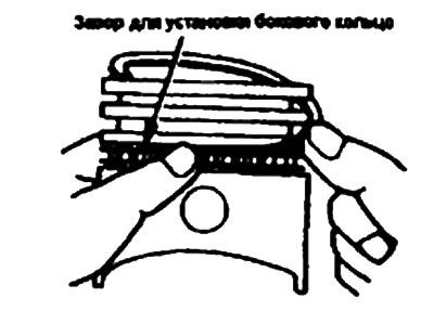
2. Install the upper side ring. To install this ring, insert one end of it between the wall of the piston ring groove and the spacer ring, press it to the bottom of the groove and, pressing with your finger as shown in the figure, insert the upper side ring into the groove.
Warning: Do not use a piston ring expander when installing side rings
3. Install the lower side ring in the same way.
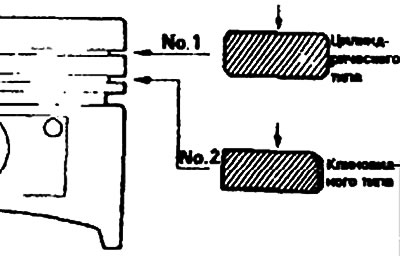
4. Using a piston ring expander, install piston ring No.2.
5. Install piston ring No.1.
6. Apply engine oil to the outer surfaces of the piston and piston rings.
7. Arrange the piston rings so that the gaps in the joints of adjacent piston rings are spaced as far apart as possible. Make sure that these gaps are not located in the plane of the piston pin axis and load bearing.
8. When installing the piston into the cylinder, press the piston rings into the piston grooves using a crimping tool.

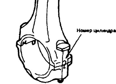
9. Make sure that the mark indicating the front of the piston and the mark indicating the front of the connecting rod (identification mark) are facing toward the front of the engine.
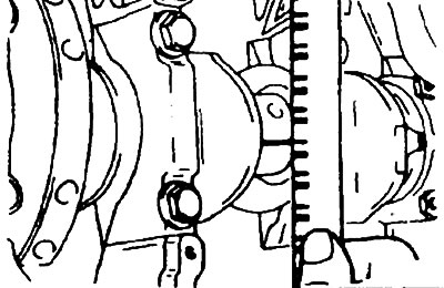
10. When installing the lower connecting rod head cover, make sure that the marks corresponding to the cylinder number on the connecting rod and cover match.
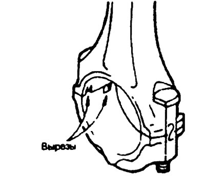
11. When installing a new connecting rod, make sure that the cutouts for retaining the bearing shells are located on the same side.
- Tightening torque: Connecting rod lower head cover fastening nuts - 50-52 Nm.
12. Tighten the connecting rod lower head cap nuts.
13. Check the bearing clearance, for which:
- 1) Remove oil and dirt from bearings and journals.
- 2) Cut a piece of plastic template the same length as the width of the bearing and place it along the journal axis away from the lubrication holes.
- 3) Install the bearing shells and cover and tighten them to the specified torque. Do not turn the crankshaft during this operation.
- 4) Remove the bearing caps and, using the scale printed on the cap, measure the thickness of the widest part.
- Connecting rod lower head cover: Bearing clearance - 0.02-0.05 mm.
14. Check the connecting rod side clearance.