
Removal
Remove the cylinder head, timing belt sprockets, front cover, flywheel, pistons and crankshaft.
Examination
Cylinder block
1. Visually check the cylinder block for scoring and rust. At the same time, check for cracks and other defects. If there are any defects, repair the block or replace it.
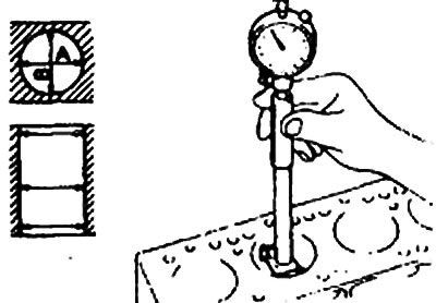
2. Using an indicator, measure the diameter of the cylinders at three levels in mutually perpendicular directions A and B.
- Level 1: Location of piston ring #1 when the piston is at top dead center.
- Level 2: Cylinder Center
- Level 3: Bottom of the Cylinder
3. If the cylinders are excessively out of round or taper, and the cylinder bore is heavily worn or scored, the cylinder block should be bored and honed, after which oversized pistons and piston rings should be installed.
Nominal value:
- Cylinder diameter - 80.60-80.63 mm
- Out of roundness or taper of the cylinder - Max. 0.01 mm
4. If the top of the cylinder is worn and has steps, cut them off with a reamer.
5. Oversized pistons are available in four sizes.
Piston size and marking, mm
- 0,25 O.S — 0,25
- 0,50 O.S — 0,50
- 0,75 O.S — 0,75
- 1,00 O.S — 1,00
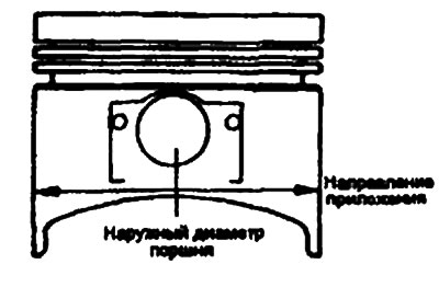
6. When reboring cylinders to a larger size, take a certain clearance between the oversized piston and the cylinder and make sure that all pistons used are the same size. The standard measurement of the piston outside diameter is taken at a distance of 2 mm from the edge of the piston skirt on the pressure-bearing surfaces.
- The gap between the piston and the cylinder mirror is 0.01-0.03 mm
7. Check for damage and cracks.
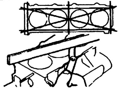
8. Check the top surface for flatness. If there is excessive flatness, grind to the minimum limit or replace the block.
Nominal value:
- Non-flatness of the upper surface of the block - Max. 0.05 mm
- Overall height - 290 mm
Limit values:
- Non-flatness of the upper surface of the block - 0.1 mm
- Total height - 0.2 mm
Warning: The top surface of the cylinder block must be ground to within -0.2 mm, as well as the bottom surface of the cylinder head.
Cylinder boring
1. The oversize pistons used should be determined based on the largest cylinder size.
| Size | Identification tag |
| 0.25 mm OS | 0.25 |
| 0.50 mm OS | 0.50 |
| 0.75 mm OS | 0.75 |
| 1.00 mm OS | 1.00 |
Note: The size mark is applied to the piston head.
2. Measure the outside diameter of the pistons used.
3. Based on the measurement results of the piston outside diameter, calculate the cylinder diameter after processing.
Cylinder diameter after boring - piston outer diameter + (0,01—0,03) mm (gap between the piston and the cylinder mirror) - 0.02 mm (permissible honing limit).
4. Bore each cylinder to the calculated size.
Warning: To prevent cylinder block deformation due to increased temperature during honing, bore the cylinders in the following order: 2-4-1-3.
5. After honing the cylinders, bring them to the required size (outer diameter of the piston + clearance between the piston and the cylinder bore).
Note: When reboring cylinders, make sure all four cylinders are the same size. Do not rebor only one cylinder to a larger size.
Assembly
1. Install the following parts following the instructions given in the relevant paragraphs.
- 1) Crankshaft.
- 2) Flywheel
- 3) Pistons.
- 4) Cylinder head.
- 5) Toothed pulleys of the toothed belt.
- 6) Front cover.
Oil pressure sensor
1. If the oil pressure warning light comes on when the ignition is turned on and goes out when the engine starts and runs at idle, then everything is fine. If the oil pressure warning light does not come on when the ignition is turned on, check the sensor, lamp and wiring.
2. If there is electric current when the ignition is turned on and there is no current when the engine is idling, the sensor is OK.
If the sensor is OK, check the lamp and wiring.
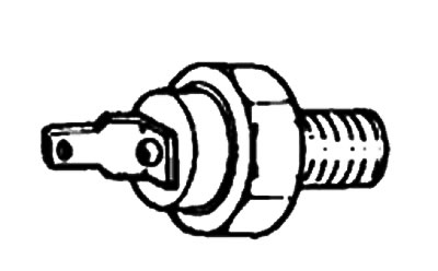
3. Using a special tool (09260— 32000), tighten the sensor to the required torque.
Note: Do not overtighten the oil pressure sensor
- Oil pressure sensor response pressure - 14.71-29.42 kPa
- Tightening torque: Oil pressure sensor - 8-12 Nm
Examination
1. Using an ohmmeter, check the electrical conductivity between the terminal and the sensor body. If there is no electrical conductivity, replace the sensor.
2. Check for electrical conductivity between the terminal and the sensor body by inserting a thin wire into it. If there is electrical conductivity even when pressing with the wire, replace the sensor.
3. No electrical conductivity when applying vacuum through the oil hole indicates normal operation of the sensor. Check for air leaks. Air leaks indicate that the diaphragm is torn. Replace the sensor.