Removal
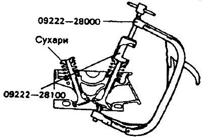
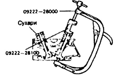
1. Using a special tool (09222—21001), remove the crackers. Remove the upper plate, valve spring, lower plate and valve.
Note: Lay out all removed parts in the order in which they should be reinstalled.
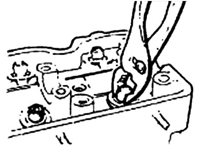
2. Use pliers to remove the sealing caps.
Warning: Do not reuse them.
 |
 |
Examination
Valve bushings
Check the clearance between the valve stem and the bushing. If this clearance exceeds the permissible limit, replace the valve bushing with a new one.
Clearance between valve stems and bushing:
Nominal value:
- Inlet valve - 0.03-0.05 mm
- Exhaust valve - 0.05-0.09 mm
Limit value:
- Inlet valve - 0.10 mm
- Exhaust valve - 0.15 mm
| Size, mm | Size mark | Cylinder head hole diameter, mm |
| 0,05 OS | 5 | 13,050-13,068 |
| 0,25 OS | 25 | 13,250-13,268 |
| 0,50 OS | 50 | 13,500-13,518 |
OS - Increased size.
Valve springs
1. Check the free height of each valve spring and replace it if necessary.
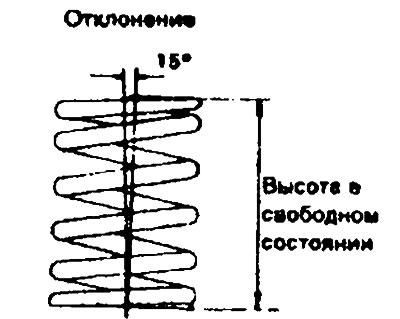
2. Using a square, check the perpendicularity of the ends of each spring to its axis. If the deviation is excessive, replace the spring.
Nominal value:
- Length in free state - 49.8 mm
- Force - 329 N/40.4 mm
- Deviation from perpendicularity - Maximum 2°
Limit value:
- Length in free state - 48.8 mm
- Force - 329 N/41.4 mm
- Deviation from perpendicularity - Maximum 4°
Valve seat restoration
1. When repairing, check the valve bushing for wear. Replace the worn bushing, and then repair the valve seat.
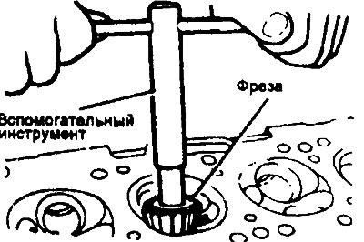
2. Correct the valve seat using a valve seat cutter and auxiliary tool.
3. After correction, the valve and its seat must be lapped using lapping paste.
Valve seats
1. Check the valve seat for signs of overheating and improper contact with the valve working chamfers. If necessary, correct or replace the valve seat.
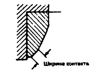
2. The width of the valve seat contact strip must correspond to the given value.
Valve seat contact strip width:
- Inlet valve - 0.9-1.3 mm
- Exhaust valve - 1.2-1.6 mm
Installation
1. Install the lower spring plates.
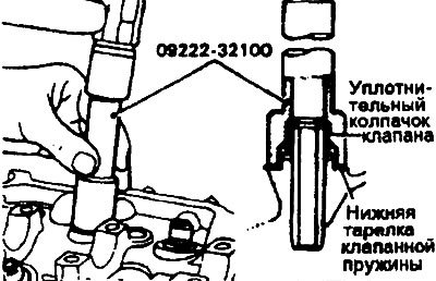
2. Using a special tool (09222—32100), gently push the lower plate into place. The sealing cap is installed in place using a special tool.
Warning:
- Do not reuse old sealing caps.
- Incorrect installation of the sealing cap will cause it to become eccentric and, as a result, oil will leak along the valve sleeve.
3. Lubricate each valve with engine oil. Install the valves into the bushings. Do not force the valves into the sealing caps. After installation, check the smooth movement of the valves.
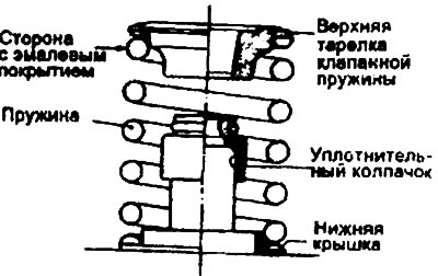
4. Valve springs are installed with the enamel coated side facing the upper plates.
 |
 |
5. Using a special (09222—21001) or other suitable tool, compress the spring and install the crackers. After installing the valves, check that the crackers are installed correctly.
Caution: When compressing the spring with a valve spring compressor or appropriate tool, make sure that the sealing cap is not compressed by the bottom of the upper spring plate.