
To check and adjust the valve clearance of the G4GC engine, you must:
1. Remove the engine cover.
Note: Checking and adjusting the valve clearance is performed on a cold engine (engine temperature 20°C) with the cylinder head installed.
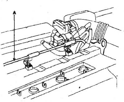
2. Loosen the mounting bolts and remove the upper drive belt cover.
3. Disconnect the high-voltage wires from the spark plugs.
Note: When disconnecting the spark plug wires, do not pull or bend the wires as this may damage the wires.
4. Disconnect the exhaust gas recirculation hose (A) and breather hose (B) from the cylinder head cover.
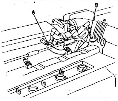
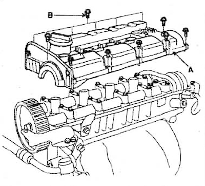
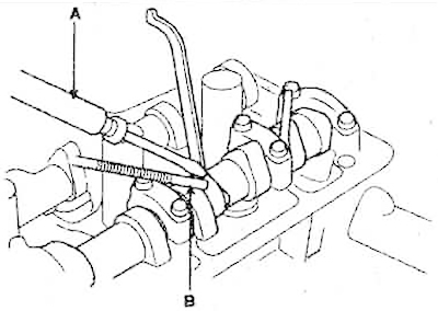
5. Disconnect the throttle cable (A) from the cylinder head cover.
6. Loosen the mounting bolts (B) and remove the cylinder head cover.
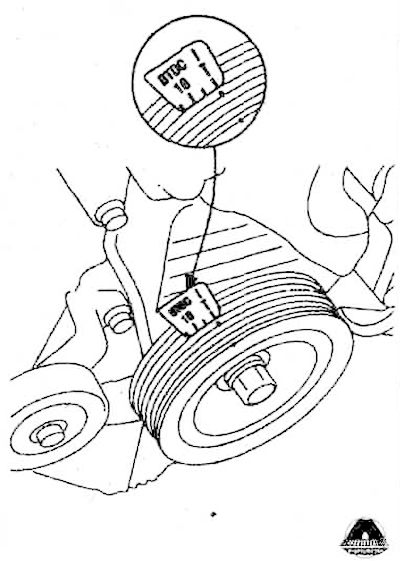
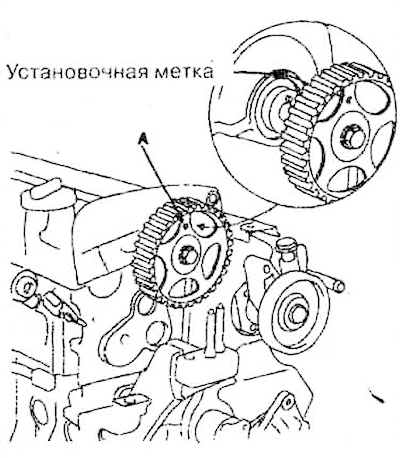
7. Set the piston of the first cylinder to the top dead center position. To do this, turn the crankshaft pulley and align the recess on the pulley with the "T" mark on the lower cover of the drive belt, as shown in the figure.
8. Make sure that the hole on the camshaft gear matches the timing mark on the bearing cap. If the hole does not match the timing mark, turn the crankshaft one full revolution (360°).
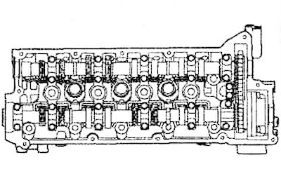
9. Check the valve clearances marked in the figure (the position of the piston of the first cylinder at the top dead center). Using a feeler gauge, check the clearance between the cams and the hydraulic valve lifters. Write down the clearance values, they will be needed later to select the valve adjusting washers.
Note.
Valve clearances (at engine temperature 20C):
- Inlet: 0.20 mm
- Graduation: 0.28 mm
Maximum permissible valve clearances:
- Inlet: 0.12-0.28 mm
- Graduation: 0.20-0.38 mm
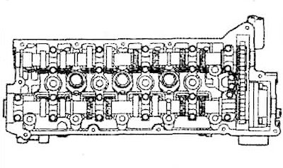
10. Turn the crankshaft one revolution and again align the recess on the crankshaft pulley with the "T" mark on the lower drive belt cover.
11. Check the clearance size of the valves shown in the figure.
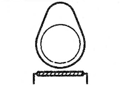
12. Adjust the clearances of the intake and exhaust valves. To do this, turn the crankshaft so that the protruding part of the cam whose clearance needs to be adjusted is directed upwards (see figure).
13. Using a special device (09220-2D008), press down on the valve thrust washer and place the stopper between the thrust washer and the camshaft. Then remove the device.
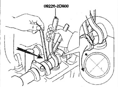
14. Using a screwdriver (A) and a magnet (B), remove the adjusting washer.
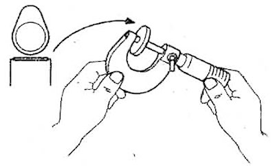
15. Measure the thickness of the removed adjusting washer with a micrometer.
16. Calculate the thickness of the new adjusting washer so that the valve clearance value corresponds to the nominal value.
- T - thickness of the removed adjusting washer.
- A is the value of the measured gap.
- N - thickness of the new adjusting washer.
- Inlet valve: N=T+(A-0.20mm)
- Exhaust valve: N=T+(A-0.28mm)
17. Select a new adjusting washer whose thickness is closest to the calculated value.
Note: The range of shims includes twenty sizes from 2.00 mm to 2.76 mm in 0.04 mm increments.
18. Install a new adjusting washer into the valve lifter.
19. Using a special device (09220-2D008), press down on the valve hydraulic compensator and remove the stopper between the thrust washer and the camshaft.
20. Recheck the valve clearance.
Thickness of new adjusting washers
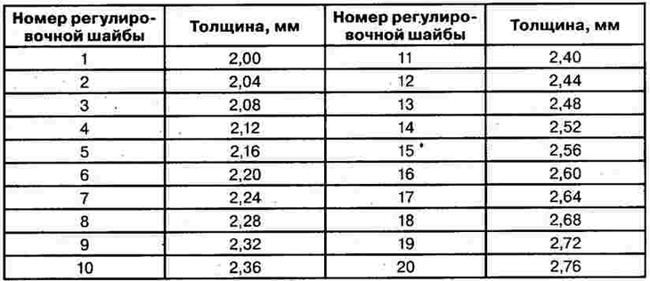
Note: The thickness of the new adjusting washers (in mm) is stamped on their front side.