
Contents: Adjusting the valve clearances when…⇓ Adjusting the valve clearances when…⇓ Valve clearance (at engine coolant…⇓ Installation ⇓ Timing chain guide ⇓ Checking the timing chain ⇓ Installation ⇓
Checking and adjusting the clearances in the valve drive is performed on a cold engine (with a coolant temperature of 20°C and the cylinder head installed on the engine.
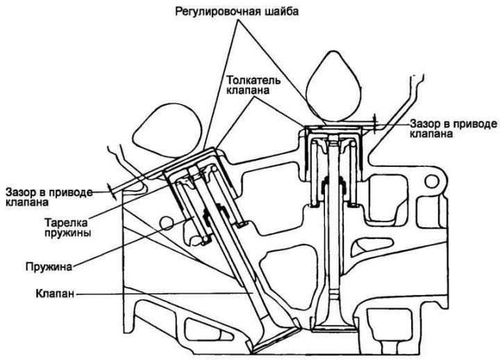
Fig. 2.100. Camshaft valve drive
Remove the engine noise shield.
Remove the oil filler cap.
Loosen the bolts securing the center cover and then remove the cover.
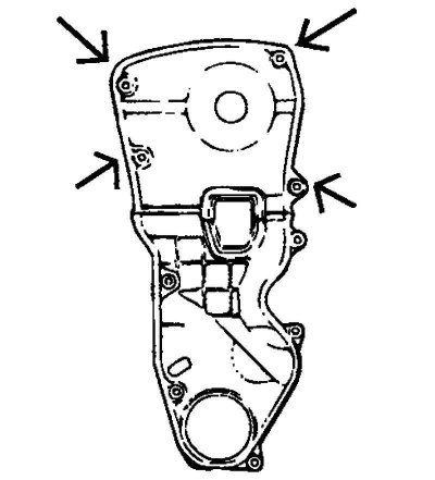
Fig. 2.101. Upper timing belt cover
Remove the upper timing belt cover (Fig. 2.101).
Loosen the timing belt upper cover mounting bolts and then remove the cover.
Remove the cylinder head cover.
Disconnect the spark plug wires by holding them by the caps and not using too much force when disconnecting them.
Note: Pulling or bending the high voltage wire may damage the conductor inside the wire.
Disconnect the positive crankcase ventilation hose and the positive crankcase ventilation valve vent hose from the cylinder head cover.
Disconnect the accelerator pedal cable from the cylinder head cover.
Loosen the cylinder head cover mounting bolts and then remove the cover and gasket.
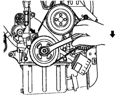
Fig. 2.102. Setting the piston of cylinder No.1 to TDC of the compression stroke
Set the piston of cylinder No.1 to TDC of the compression stroke (Fig. 2.102).
Turn the crankshaft pulley and align the groove on it with the timing mark "T" on the injection advance angle indicator (scale on the lower timing belt cover).

Fig. 2.103. Aligning the camshaft sprocket with the timing mark on the front bearing cover
Check that the hole in the camshaft sprocket (for the belt) is aligned with the timing mark on the camshaft front bearing cap. If not, rotate the crankshaft one revolution (360°) (Fig. 2.103).
Check the valve clearances.
Check only the valves marked in the figure (when the piston of cylinder #1 is at TDC compression). Measure the clearance in the valve drive.
Using a flat feeler gauge, measure the clearance between the valve tappet adjusting washer and the surface of the rear (non-working) part of the cam.
Record the clearance measurements in places where the measured value does not correspond to the permissible values. This data will be required later to select a replacement adjusting washer.
Valve clearance values (at engine coolant temperature: 20°C) are given below.
Nominal value:
- inlet valves - 0.20 mm;
- exhaust valves - 0.28 mm.
Maximum permissible value:
- inlet valves - 0.12–0.28 mm;
- exhaust valves - 0.20–0.36 mm.
Adjusting the valve clearances when the piston of cylinder No.1 is at TDC of the compression stroke
Turn the crankshaft pulley one revolution (360°) and align the groove on it with the installation mark "T" on the injection advance angle indicator (scale on the lower timing belt cover).
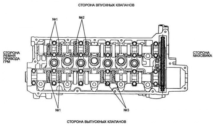
Fig. 2.104. Checking the clearances in the valve drive when the piston of cylinder No.1 is at TDC of the compression stroke
Check only the valves marked in Figure 2.104 when the piston of cylinder No.4 is at TDC compression. Measure the clearance in the valve drive.
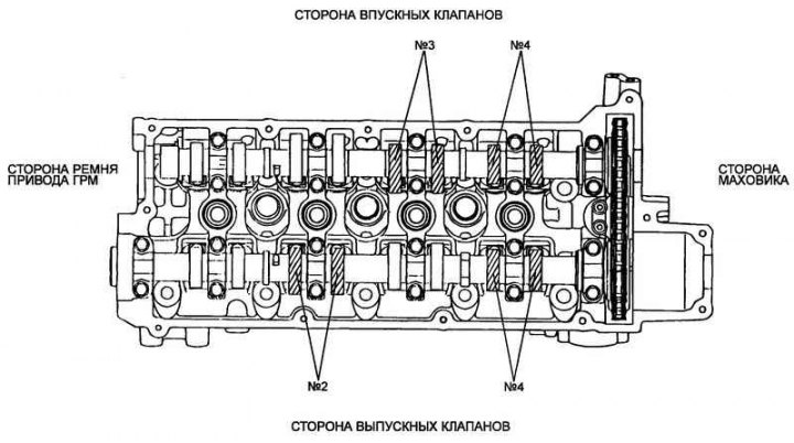
Fig. 2.105. Checking the clearances in the valve drive when the piston of cylinder No.4 is at TDC of the compression stroke
Adjusting the valve clearances when the piston of cylinder #4 is at TDC of the compression stroke
Adjusting clearances in the intake and exhaust valve drives.
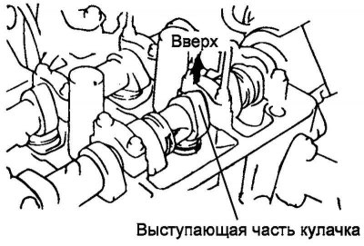
Fig. 2.106. Installing the camshaft cam
Turn the crankshaft so that for the valve in whose drive the clearance is adjusted, the protruding part of the camshaft cam is directed upwards (Fig. 2.106).
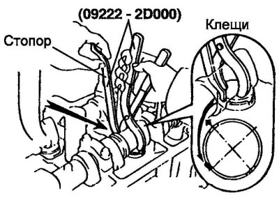
Fig. 2.107. Installing the stopper between the camshaft and the valve tappet
Using special tool 09220-2D000, press the valve tappet and insert the stopper between the camshaft and the valve tappet. Remove the special tool (Fig. 2.107).

Fig. 2.108. Removing the adjusting washer
Using a small screwdriver and a magnet, remove the adjusting washer (Fig. 2.108).
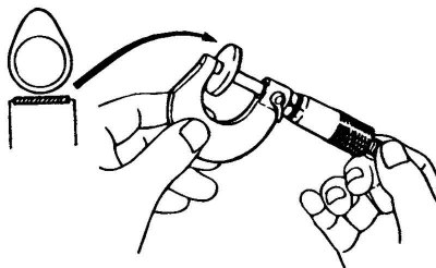
Fig. 2.109. Measuring the adjusting washer
Using a micrometer, measure the thickness of the removed adjusting washer (Fig. 2.109).
Calculate the thickness of the new adjusting shim that must be installed to ensure that the valve clearance matches the nominal value.
Valve clearance (at engine coolant temperature: 20°C)
T: Thickness of the installed adjusting washer
A: Measured valve clearance.
N: Thickness of new adjusting washer.
- Inlet valve: N=T+(A–0.20) mm.
- Exhaust valve: N=T+(A–0.28) mm.
Select a new shim with a thickness as close as possible to the calculated value.
Note: There are 20 valve tappet shim sizes available in 0.04mm increments ranging from 2.0mm to 2.76mm.
Install the selected adjusting washer onto the valve lifter.
Using special tool 09220-2D000, press on the valve tappet and remove the stopper.
Check the valve drive clearance again.
Installation
Remove any remaining old gasket and sealant from the mating surfaces of the cylinder head and cylinder head cover.
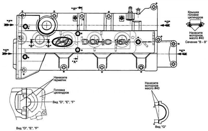
Fig. 2.110. Places where sealant is applied to the cylinder head cover
Apply sealant (Loctite № 5999) on the cylinder head cover (Fig. 2.110).
Install the cylinder head cover.
Tightening torque of cylinder head cover bolts: 8–10 Nm.
Connect the accelerator pedal cable.
Connect the positive crankcase ventilation hose and the positive crankcase ventilation valve vent hose to the cylinder head cover.
Connect the high tension spark plug wires to the spark plugs.
Install the upper timing belt cover and tighten the four mounting bolts.
Install the center cover and tighten the five mounting bolts.
Tightening torque of the central cover mounting bolts: 2.5–3.5 N·m.
Install the oil filler cap.
Install the engine noise protection cover.
Timing chain guide
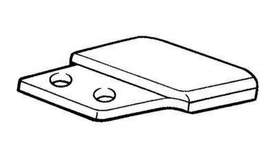
Fig. 2.111. Chain guide
Check the chain guide for bending, cracks or other defects (Fig. 2.111).
Check the chain guide rubber pad for excessive wear.
Replace the chain guide if necessary.
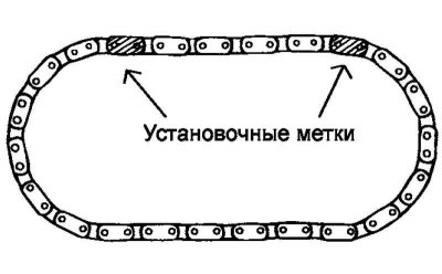
Fig. 2.112. Timing chain
Checking the timing chain
Check the chain components (bushings and plates) for wear. Replace the chain if wear is excessive.
Installation
Install the hydraulic lifters back into place.
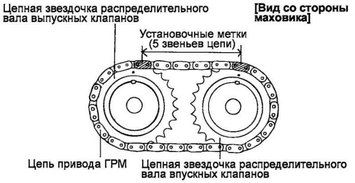
Fig. 2.113. Alignment of the timing chain with the chain sprockets of the intake and exhaust camshafts
Align the timing chain with the intake and exhaust camshaft sprockets as shown in Figure 2.113.
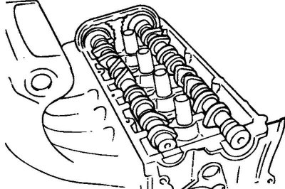
Fig. 2.114. Installing camshafts
Lubricate the camshaft bearing journals with engine oil, then install the camshaft in place (Fig. 2.114).
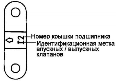
Fig. 2.115. Identification marks on bearing caps
Install the camshaft bearing caps. The identification marks on the bearing caps are intended to identify the installation location of the cap (inlet/outlet valve side) (Fig. 2.115).
- I: Intake camshaft.
- E: exhaust camshaft.
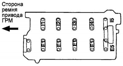
Fig. 2.116. Tightening order of camshaft bearing cap bolts
Tighten the camshaft bearing cap mounting bolts to the specified tightening torque in two or three steps in the order indicated by the numbers in Figure 2.116.
Tightening torque of the camshaft bearing cover bolts: 12–14 N·m.
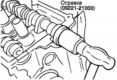
Fig. 2.117. Pressing in the camshaft seal using a special tool
Using a special tool (mandrel for installing camshaft seal 09221-21000), press in the camshaft seal (Fig. 2.117).
Make sure the camshaft oil seal lip is lubricated with engine oil. Position the seal on the camshaft from the timing belt sprocket side, then tap the seal with a hammer on the mandrel until it is flush with the surface.
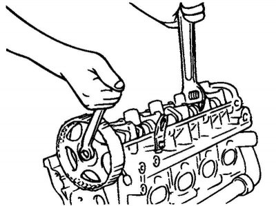
Fig. 2.118. Installing the camshaft sprocket
Install the sprocket (for the belt) of the camshaft and tighten its mounting bolt to the nominal tightening torque (Fig. 2.118).
Tightening torque of the camshaft sprocket mounting bolt (for belt): 80–100 N·m.
Align the marks on the crankshaft and camshaft sprockets with the corresponding timing marks and set the piston of cylinder No.1 to TDC of the compression stroke.
Install the cylinder head cover.
Tightening torque of cylinder head cover bolts: 8–10 Nm.
Install the ignition coil assemblies, spark plug wires and center cap.
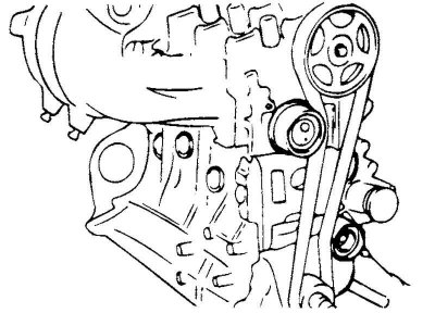
Fig. 2.119. Installing the timing belt
Install the timing belt and then, when the tensioner roller tensions the belt, tighten the tensioner fastening (Fig. 2.119).
Install the timing belt covers.
Tightening torque of timing belt cover mounting bolts: 8–10 N·m.
Install the coolant pump pulley and crankshaft pulley.
This article is based on information from the website hyundaibook.ru