
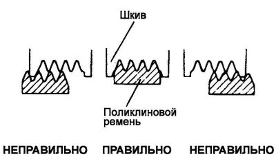
Fig. 2.91. Correct seating of the belt in the pulley grooves
Check that the belt is correctly seated in the pulley grooves (Fig. 2.91).
Apply a force of 100 N to the back (non-working) side of the belt in the middle of the branch between the two pulleys. Measure the belt deflection using a tension meter.
Attention! When installing the poly V-belt, make sure that the belt raceways are correctly seated in the pulley grooves.
Caution! If the belt squeals or slips during operation, check the contact surfaces with the pulleys and the pulley itself for wear, damage or delamination. In addition, check the degree of belt tension.
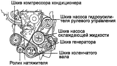
Fig. 2.92. Attachment drive belt outline
Note: Belt tension is measured at the midpoint of the belt run between the pulleys shown.
Note: When installing a new belt, adjust the tension so that it matches the middle value of the allowable range in the "for new belt" column tables 2.11. After installing the belt, let the engine run for 5 minutes or longer, then check whether the belt tension matches the standard value in the "when checking" column tables 2.11.
Note: When adjusting a used belt or a new belt that has been running on the engine for more than 5 minutes, use the nominal values given in the column "for a used belt" tables 2.11.
Note: When checking the belt tension periodically, use the nominal values given in the "when checking" column tables 2.11.
Tension Meter - Type "A"
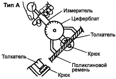
Fig. 2.93. Tension meter – type "A"
(The original text is published on the website HYUNDAIBOOK.RU)
Do not allow the dial of the meter to touch anything when taking measurements (Fig. 2.93).
Tension Meter - Type "B"
When taking measurements, turn the "RESET" knob in the direction indicated by the arrow and set the pointer to the "RESET" position.
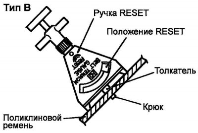
Fig. 2.94. Tension meter – type "B"
If the tension gauge is removed from the belt, the pointer will remain in the position corresponding to the tension value. Read the readings after removing the tension gauge (Fig. 2.94).