
Contents: Disassembly ⇓ Examination ⇓ Checking the main and connecting rod…⇓ Measuring bearing clearance ⇓ Checking the crankshaft seals ⇓ Checking bearing caps ⇓ Checking the Crankshaft Position…⇓ Assembly ⇓
Disassembly
Remove the timing belt, oil pump housing, flywheel, cylinder head assembly and oil pan. Refer to the appropriate sections for part removal procedures.
Remove the rear plate of the cylinder block and the rear crankshaft oil seal.
Remove the connecting rod caps and connecting rod bearing shells from the crankshaft.
Remove the crankshaft main bearing caps and remove the crankshaft. Arrange the main bearing shells in the order in which they correspond to the cap numbers.
Remove the crankshaft position sensor rotor.
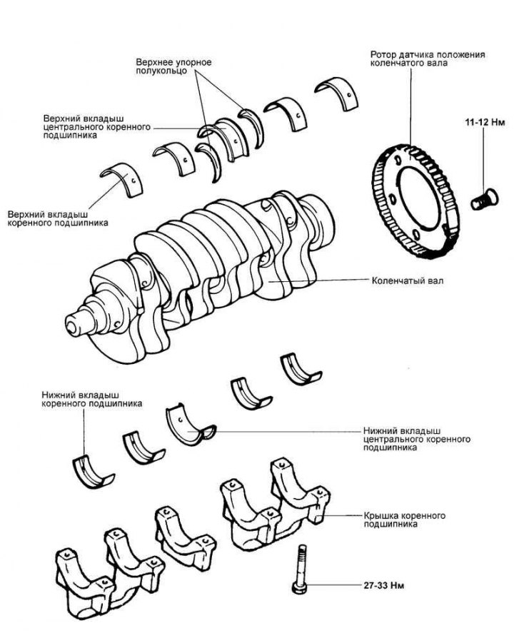
Fig. 2.120. Crankshaft components
Note: To simplify installation, arrange the removed parts (connecting rod caps, connecting rod and main bearing shells) in the order of their cylinder numbers and orientation at the installation location.
Examination
Check the crankshaft main and connecting rod journals for damage (scoring and seizure), excessive wear and cracks. Also check the oil passage holes for blockage. Repair or replace the faulty part.
Check the taper and out-of-roundness of the crankshaft main and connecting rod journals.
Nominal value:
- main journal diameter - 57 mm;
- crank pin diameter - 45 mm;
- taper and out-of-roundness of main and connecting rod journals - 0.1 mm or less.
Checking the main and connecting rod bearing shells
Visually inspect the surface condition of each bearing (peeling, uneven contact, scratches, scoring, etc.). Replace defective bearings.
Measuring bearing clearance
Measure the diameter of the main and connecting rod journals of the crankshaft.
Measure the inside diameters of the main bearing holes in the crankshaft bed (in the cylinder block and bearing cap) and the connecting rod bearing holes (in the small connecting rod head and connecting rod cap).
Measure the thickness of the connecting rod and main bearing shells.
Calculate the clearance in the bearings based on the results of the measurements taken (you need to subtract the shaft journal diameter and the bearing shell thickness from the value of the internal diameter of the bearing hole).
- Connecting rod bearing clearance: 0.28–0.48 mm.
- Main bearing clearance (established limit for new parts): 0.024–0.044 mm.
Checking the crankshaft seals
Check the front and rear crankshaft oil seals for damage or wear on the working edges. If there are any defects, replace the oil seal.
Checking bearing caps
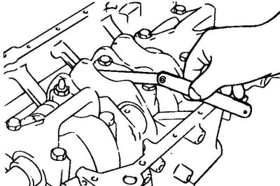
Fig. 2.121. Checking the axial clearance of the crankshaft
After installing the main bearing caps, check that the crankshaft rotates smoothly and that the crankshaft axial clearance corresponds to the nominal value. If the axial clearance exceeds the maximum permissible value, replace the bearing thrust half rings and/or bearing shells (Fig. 2.121).
- Nominal value: 0.06–0.26 mm.
- Maximum permissible value: 0.30 mm.
Checking the Crankshaft Position Sensor Rotor
Remove the crankshaft position sensor rotor.
Check the crankshaft position sensor rotor for damage, cracks, and wear. Replace the sensor rotor if necessary.
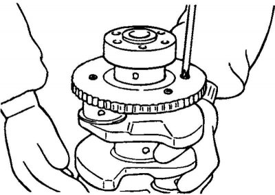
Fig. 2.122. Checking the gap between the sensor rotor tooth and the sensor tip using a depth gauge
Check the gap between the sensor rotor tooth and the sensor tip using a depth gauge (Fig. 2.122).
The nominal value of the gap between the sensor rotor tooth and the sensor tip: 0.5–1.1 mm.
Note: Measure the distance from the top of the crankshaft position sensor rotor tooth to the sensor mounting surface on the cylinder block.
Note: Measure the length of the crankshaft position sensor tip as the distance between the end of the sensor tip and the sensor mounting plane.
Note: Calculate the gap as the difference between the values given.
Assembly
Install the upper main bearing shells into the crankshaft bed on the cylinder block.
Note: Be careful when installing the main bearing shells removed earlier during disassembly, position them in accordance with the installation marks made before removal.
Install the crankshaft. Apply engine oil to the crankshaft main journals.
Install the lower bearing shells and main bearing caps. Tighten the cap mounting bolts to the specified tightening torque in the following sequence: center bearing cap, bearing cap No.2, bearing cap No.4, front bearing cap, and rear bearing cap.
Tighten the bolts gradually in two or three stages, then tighten to the specified torque.
When installing, the covers must be positioned so that the arrows on the covers point towards the crankshaft pulley and the cover numbers correspond to the cylinder numbers.
Tightening torque of main bearing cap bolts: 27–33 N·m (60–65°), connecting rod cap bolts: 50–53 N·m.
Check again that the crankshaft rotates smoothly and that the crankshaft axial clearance (the clearance between the thrust flange of the central main bearing and the corresponding crankshaft web) corresponds to the nominal value.
The nominal value of the crankshaft axial clearance is 0.06–0.26 mm.
Using a special tool (crankshaft rear oil seal installation tool 09231-2100), install the crankshaft rear oil seal into the oil seal housing as shown in the figure. Be careful to position the tool correctly to avoid damaging or deforming the oil seal during installation.
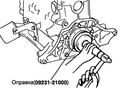
Fig. 2.123. Installing the rear crankshaft oil seal
Install the rear plate of the cylinder block and tighten its mounting bolts.
Install the connecting rod caps.
Install the flywheel, oil pump housing, oil pan and timing belt. The installation procedures for the parts are given in the appropriate sections.