
Contents: Disassembly ⇓ Checking the crankshaft ⇓ Checking the main and connecting rod…⇓ Measuring bearing clearance ⇓ Measuring bearing clearance using a…⇓ Checking the crankshaft seals ⇓ Checking bearing caps ⇓ Checking the automatic transmission…⇓ Checking the flywheel ⇓ Assembly ⇓
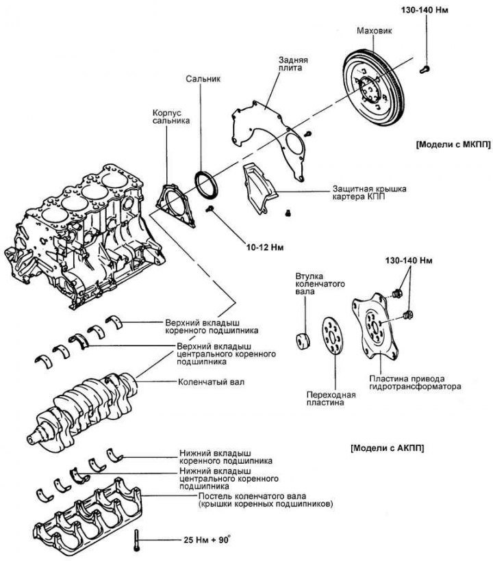
Fig. 2.113. Crankshaft and flywheel
Disassembly
Remove the timing belt, front cover, flywheel, cylinder head and oil pan.
Remove the rear plate of the cylinder block and the rear crankshaft oil seal.
Remove the connecting rod caps and connecting rod bearing shells.
Note: For proper subsequent installation, arrange the removed parts (connecting rod caps, connecting rod and main bearing shells) in the order of their cylinder numbers and orientation at the installation location.
Remove the main bearing cap block and crankshaft. Arrange the main bearing shells in order of their cylinder numbers.
Checking the crankshaft
Check the crankshaft main and connecting rod journals for damage (scoring and seizure), excessive wear and cracks. Clean the shaft oil passages. Repair or replace the crankshaft if necessary.
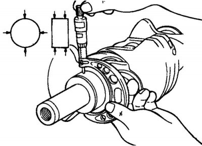
Fig. 2.114. Diagram of measuring the taper and out-of-roundness of the main and connecting rod journals of the crankshaft
Check the taper and out-of-roundness of the main and connecting rod journals of the crankshaft (Fig. 2.114).
The nominal value of the measured diameters is given below.
Main journal diameter: 56.982–57.000 mm.
Crankpin diameter: 44.980–45.000 mm.
Taper and out-of-roundness of main and connecting rod journals: 0.01 mm or less.
Checking the main and connecting rod bearing shells
Visually inspect the surface condition of each bearing (peeling of the friction layer, uneven contact, scratches, scoring, etc.). Replace defective bearings.
Measuring bearing clearance
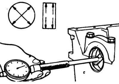
Fig. 2.115. Diagram of measuring the internal diameters of the holes for the main bearings in the crankshaft bed using a bore gauge
Measure the diameter of the main and connecting rod journals of the crankshaft. Measure the internal diameters of the holes for the main bearings in the crankshaft bed (in the cylinder block and bearing cap) and the holes for the connecting rod bearings (in the lower head and connecting rod cap). Measure the thickness of the connecting rod and main bearing shells. Calculate the bearing clearance based on the results of the measurements (you need to subtract the shaft journal diameter and two values of the bearing shell thickness from the value of the internal diameter of the bearing hole) (Fig. 2.115).
Main bearing clearance:
- Necks No.1,2,4,5 - 0.018–0.036 mm;
- Neck No.3 - 0.024–0.042 mm.
Connecting rod bearing clearance: 0.015–0.048 mm.
Limit clearance: 0.1 mm.
Measuring bearing clearance using a plastic gauge
The determination of the clearance value in the main bearings of the crankshaft using the plastic gauge method is described below.
Remove oil, grease or other contaminants from the shaft journals. Wash and dry the bearing shells.
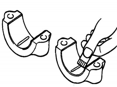
Fig. 2.116. Laying out the plastic gauge
Cut the plastic gauge into pieces equal in width to the shaft journals. Place the gauges on the journals along the shaft axis (do not place the gauge on the oil supply holes) (Fig. 2.116).
Install the bearing shells, crankshaft and main bearing cap block. Tighten the cap block mounting bolts to the specified tightening torque. Do not rotate the crankshaft. Remove the cap block. Measure the maximum width of the flattened part of the gauge using the scale on the gauge envelope. Determine the bearing clearance. If necessary, repair or replace the crankshaft or bearing shells. If replacing the shell does not correct the clearance, regrind the shaft journals to the repair size and replace the shells accordingly.
Checking the crankshaft seals
Check the front and rear crankshaft oil seals for damage or wear on the working edges. If there are any defects, replace the oil seal.
Checking bearing caps
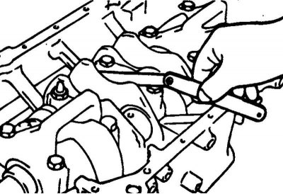
Fig. 2.117. Measuring the axial clearance of the crankshaft
After installing the main bearing cap block, make sure that the crankshaft rotates smoothly and that the crankshaft axial clearance corresponds to the nominal value. If the axial clearance exceeds the maximum permissible value, replace the bearing thrust half rings and/or bearing shells (Fig. 2.117).
Nominal value: 0.05–0.25 mm.
Checking the automatic transmission drive plate
Replace any warped or cracked plate.
Checking the flywheel
Check the flywheel for flatness before installing the clutch drive disc. If there are deep scratches or severe wear, replace the flywheel.
Check the flywheel runout.
Limit runout: 0.13 mm.
Check the condition of the flywheel ring gear teeth. Replace the ring gear if necessary.
Assembly
Install the upper main bearing shells into the crankshaft bed on the cylinder block. The upper shells have an oil distribution groove.
Install the lower bearing shells (without grooves) into the main bearing cap block bed.
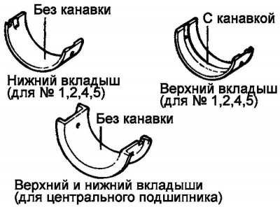
Fig. 2.118. Central neck inserts
The central journal liners (with thrust bearing) do not have oil distribution grooves (Fig. 2.118).
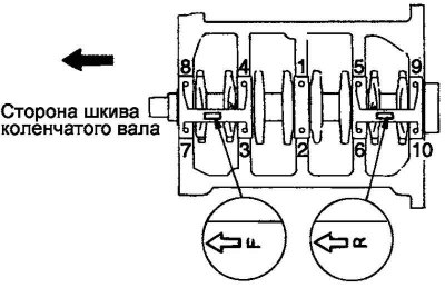
Fig. 2.119. Crankshaft installation diagram
Apply engine oil to the crankshaft main journals. Install the crankshaft (Fig. 2.119).
Install the lower bearing shells and main bearing cap assembly with the mark facing the front of the engine.
Tighten the cover mounting bolts to the specified torque.
Tightening torque of the main bearing cap bolts: 25 Nm + 90°.
Tighten the bolts gradually in four to five stages, then tighten to the specified torque. Tighten the bolts an additional 90 degrees.
Check the crankshaft for freedom of rotation and measure the axial clearance.
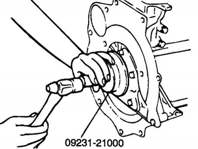
Fig. 2.120. Installing the rear crankshaft oil seal
Using a special tool (crankshaft rear oil seal installation tool 09231-2100), install the crankshaft rear oil seal into the oil seal housing as shown in Figure 2.120. Be careful to position the tool correctly to avoid damaging or deforming the oil seal during installation.
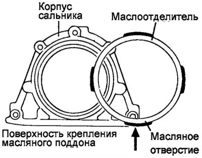
Fig. 2.121. Diagram of correct installation of the seal
Install the oil seal so that the hole (arrow in Figure 2.121) of the oil separator is directed downwards (towards the oil pan).
Install the seal housing onto the new gasket. Tighten the mounting bolts.
Tightening torque of oil seal housing mounting bolts: 10–12 N·m.
Models with manual transmission: install the rear plate of the cylinder block and tighten its mounting bolts, install the flywheel. Tighten the mounting bolts to the specified torque.
Tightening torque of flywheel mounting bolts: 130–140 Nm.
Models with automatic transmission: install the bushing and adapter on the crankshaft, install the automatic transmission drive plate. Tighten the mounting bolts to the specified torque.
Tightening torque of the automatic transmission plate mounting bolts: 130–140 N·m.