
Contents: Removal ⇓ Installation ⇓
Removal
Remove the battery.
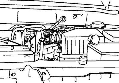
Fig. 2.64. Disconnecting the air filter duct
Disconnect the air filter duct (Fig. 2.64).
Disconnect the connectors:
- engine wiring harness (generator, starter, etc.);
- throttle position sensor;
- power steering pressure switch, oil pressure switch;
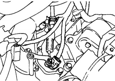
Fig. 2.65. Reverse lamp switch
- reverse light switch (Fig. 2.65);
- electromagnetic valve of automatic transmission, start inhibit switch;
- coolant temperature sensor;
- ignition coils and commutator (power transistor);
- idle air control valve;
- absolute pressure and air temperature sensors;
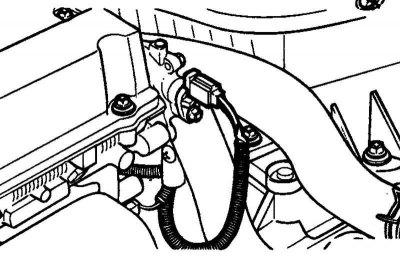
Fig. 2.66. Oxygen sensor
- oxygen sensor (Fig. 2.66).
Drain the coolant.
On models with automatic transmission, disconnect the coolant system hoses.
Note: When disconnecting the hoses, make sure to mark the alignment marks first so that the hoses can be returned to their original positions when reconnecting.
Caution: Be careful when disconnecting hoses, do not spill oil or other liquid. Plug disconnected tubes or hoses to prevent foreign particles from getting inside.
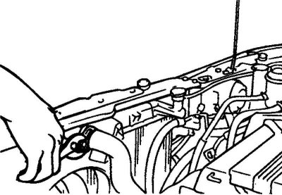
Fig. 2.67. Disconnecting the upper radiator hose
Disconnect the upper and lower radiator hoses from the engine side, then remove the radiator assembly (Fig. 2.67).
Disconnect the engine ground wire.
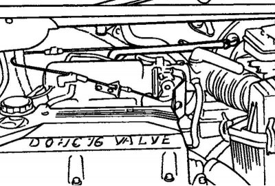
Fig. 2.68. Brake booster vacuum hose
Disconnect the brake booster vacuum hose (Fig. 2.68).
Disconnect both heater hoses (inlet and outlet) from the engine side.
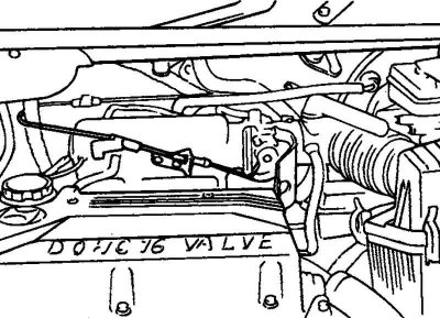
Fig. 2.69. Accelerator pedal cable
Disconnect the accelerator pedal cable from the engine side (Fig. 2.69).
Disconnect the main fuel line, fuel return hose and evaporative emission system hose from the engine side.
Disconnect the speedometer drive cable from the gearbox.
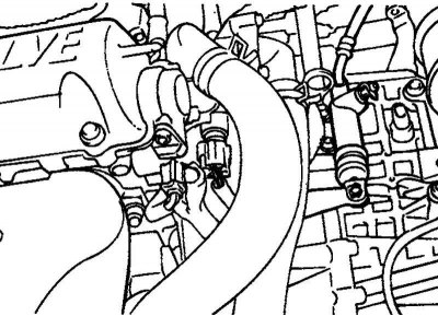
Fig. 2.70. Clutch release cable
On models with automatic transmission, disconnect the automatic transmission control cable; on models with manual transmission, disconnect the clutch release cable (Fig. 2.70).
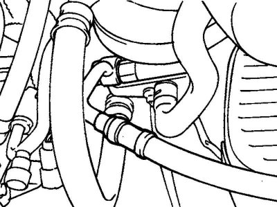
Fig. 2.71. Power steering pump hoses
Disconnect both hoses from the power steering pump (Fig. 2.71).
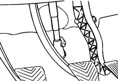
Fig. 2.72. Steering shaft cardan joint
In the engine compartment, remove the steering gear mudguard and disconnect the steering shaft cardan joint from the mechanism (Fig. 2.72).
Note: Mark the relative positions of the universal joint and steering shaft.
Raise the vehicle and remove the front wheels.
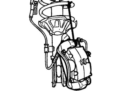
Fig. 2.73. Brake caliper
Remove the brake caliper from the steering knuckle. Hang the caliper on the stand using a wire (not by the brake hose) (Fig. 2.73).
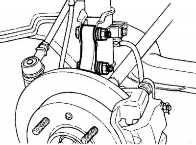
Fig. 2.74. Rack mounting bolts
Unscrew the lower bolt of the rack mount, remove the bolt (Fig. 2.74).
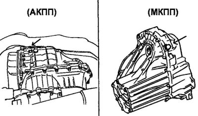
Fig. 2.75. Drain plugs for manual and automatic transmissions
Drain the oil from the gearbox (Fig. 2.75).
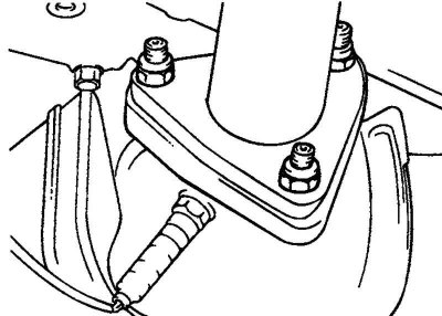
Fig. 2.76. Front muffler mounting bolts
Unscrew the front muffler mounting bolts (Fig. 2.76).
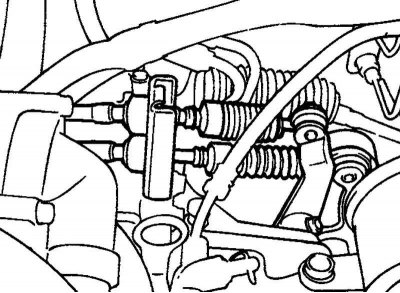
Fig. 2.77. Gear shift control rod
On models with manual transmission, remove the gear shift control rod (Fig. 2.77).
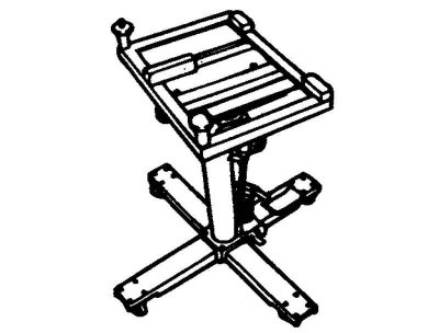
Fig. 2.78. Rolling jack
Attach a special adapter to the trolley jack and adjust it to the subframe (Fig. 2.78).
Note: Make sure all wiring connectors and control cables are disconnected from the engine and transmission.
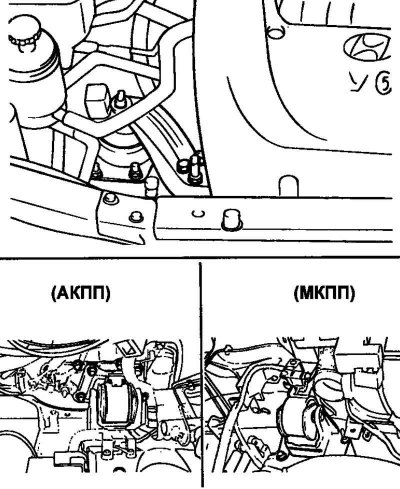
Fig. 2.79. Side engine and gearbox mounts
Remove the side engine support and gearbox support (Fig. 2.79).
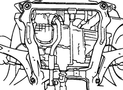
Fig. 2.80. Subframe mounting bolts
Unscrew the subframe mounting bolts (Fig. 2.80).
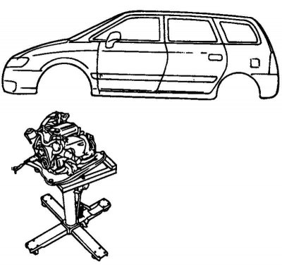
Fig. 2.81. Placing the engine on the jack
Remove the drive shafts. Lower the engine and gearbox on the jack, remove the front and rear engine mounts (Fig. 2.81).
Remove the engine and gearbox.
Installation
Before installing the power unit, check the integrity of the wires, tubes, hoses, etc. Make sure not to damage the specified parts during installation.
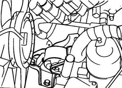
Fig. 2.82. Installing the front support cushion
Install the front support cushion onto the bracket (Fig. 2.82).
Nominal tightening torque of the support: 50–65 Nm.
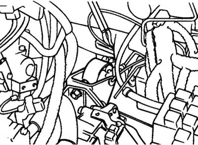
Fig. 2.83. Installing the rear support cushion
Install the rear support cushion onto the bracket (Fig. 2.83).
Nominal tightening torque of the support: 50–65 Nm.
Install the engine and gearbox assembly on the subframe. Using a trolley jack, adjust the position of the power unit relative to the body.
Install the gearbox support.
Nominal tightening torque of the support: 90–110 Nm.
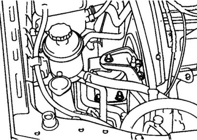
Fig. 2.84. Installing the side support bracket
Install the side engine support bracket (Fig. 2.84).
Nominal tightening torque of the support: 60–80 Nm.
Reinstall the removed parts.
Fill the cooling system and check for fluid leaks.
Fill the gearbox with working fluid.
Adjust the gearbox and accelerator control cables.
Check the operation of the pointers and indicators.