
Contents: Disassembly ⇓ Checking the cylinder head ⇓ Checking the valves ⇓ Checking valve springs ⇓ Checking the valve guides ⇓ Valve seat restoration ⇓ Replacing the valve seat ⇓ Replacing the valve guide ⇓ Assembly ⇓
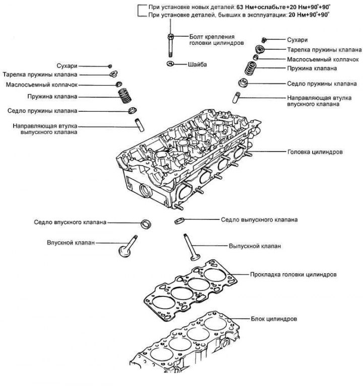
Fig. 2.122. Cylinder head and valves
Disassembly
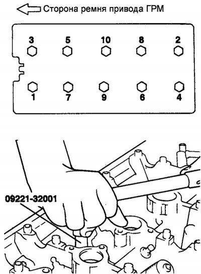
Fig. 2.123. The order of unscrewing the cylinder head mounting bolts
Using a special tool (key 09221-32001), unscrew the cylinder head mounting bolts in the order shown in Figure 2.123.
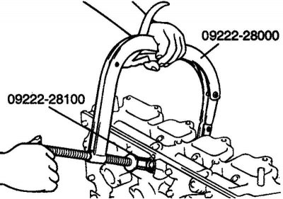
Fig. 2.124. Removing crackers
Using a special tool (valve spring compressor 09222-28000 and adapter 09222-28100), compress the spring and remove the crackers. Remove the valve spring plate, valve spring, valve spring seat and valve (Fig. 2.124).
Note: Keep the parts for each valve separately as a set to avoid mixing them up during installation.
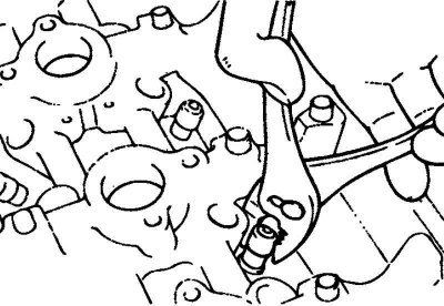
Fig. 2.125. Removing the oil seals
Using a special tool (oil seal remover 09222-29000), remove the oil seals (Fig. 2.125).
Note: Reinstallation of valve stem seals is not permitted.
Checking the cylinder head
Check the cylinder head for cracks, damage, and signs of coolant leakage. If cracks are found, replace the cylinder head.
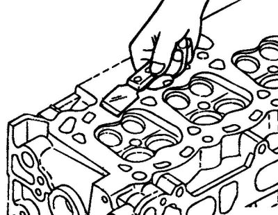
Fig. 2.126. Cleaning the cylinder head surface
Completely clean the cylinder head from scale, carbon deposits and remnants of old sealant and gasket. Clean the oil passages, blow them out with compressed air (Fig. 2.126).
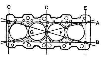
Fig. 2.127. Scheme for checking the flatness of the mating surface of the cylinder head
Check the non-flatness of the cylinder head mating surface in the directions shown in the figure. If the non-flatness exceeds the maximum permissible value in any direction, either replace the cylinder head or regrind the cylinder head mating surface (Fig. 2.127).
The values of non-flatness of the cylinder head mating surface are given below.
Nominal value: less than 0.03 mm.
Maximum permissible value: 0.2 mm.
Checking the valves
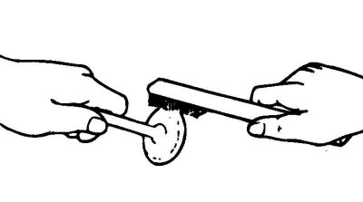
Fig. 2.128. Cleaning the valve
Using a wire brush, thoroughly clean the valve (Fig. 2.128).
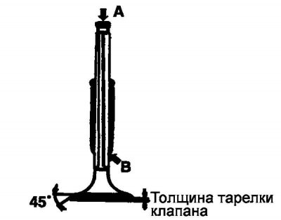
Fig. 2.129. Valve testing diagram
Check each valve for wear, damage, and deformation of the valve plate and zone "B" of the valve stem. Replace the valve if necessary. If dents have formed on the end face "A" of the valve stem or there is significant wear, then process the end face of the valve stem, if necessary. The thickness of the layer removed during mechanical processing of the end face of the valve stem should be minimal. In addition, process the working chamfer of the valve seat (Fig. 2.129).
Replace the valve if its plate thickness is less than the maximum permissible value.
Nominal value of valve plate thickness:
- inlet valve - 1.0 mm;
- outlet valve - 1.5 mm.
Maximum permissible value:
- inlet valve - 0.7 mm;
- outlet valve - 1.0 mm.
Checking valve springs
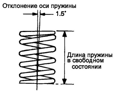
Fig. 2.130. Valve spring testing diagram
Check the length of the valve spring in the free state. If the length of the spring is less than the maximum permissible value, replace the valve spring (Fig. 2.130).
Using a square, check the deviation of the spring axis from the perpendicular to the supporting surface (non-perpendicularity). If the non-perpendicularity is greater than the maximum permissible value, replace the valve spring.
The nominal values of valve spring measurements are given below.
Free spring length: 45.82 mm.
Spring length under 25.3 kg load: 40.00 mm.
Spring axis deviation (non-perpendicularity): 1.5° or less.
The maximum allowable values for valve spring measurements are given below.
Free spring length: 44.82 mm.
Spring axis deviation (non-perpendicularity): 4°.
Checking the valve guides
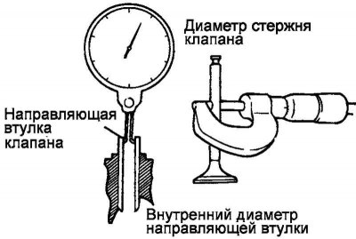
Fig. 2.131. Valve guide testing diagram
Check the clearance between the guide and the valve stem (at several points along the length). If the clearance is greater than the maximum permissible value, replace the valve guide (Fig. 2.131).
The clearance values between the guide and the valve stem are given below.
Nominal value:
- inlet valve - 0.020–0.047 mm;
- exhaust valve - 0.050–0.085 mm.
Maximum permissible value:
- inlet valve - 0.10 mm;
- outlet valve - 0.15 mm.
Valve seat restoration
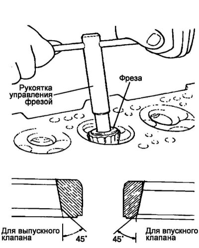
Fig. 2.132. Restoring the valve seat
Check the valve seat for signs of overheating and uneven contact with the valve plate locking chamfer. Restore or replace the valve seat if necessary. Before restoring the valve seat, check the valve guide bushing for wear. If the guide bushing is worn, replace it first and then restore the valve seat. The valve seat is restored using a special tool (milling cutters or machine tools). The width of the valve seat locking chamfer must correspond to the nominal values and the contact patch must be evenly distributed along the center of the working chamfer of the valve plate. After restoring the seat, the valve and seat must be lapped using lapping paste (Fig. 2.132).
Replacing the valve seat
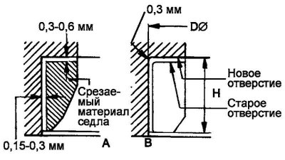
Fig. 2.133. Residual amount of metal when processing a replaceable valve seat
Cut out the valve seat to be replaced, the residual amount of metal is shown in Figure 2.133.
Ream the hole in the cylinder head to install a valve seat of the appropriate repair size (increased diameter).
Heat the cylinder head to approximately 250°C and press the oversize seat into the cylinder head.
Lapping the valve to the new seat using lapping paste.
Width of valve seat chamfer: 0.9–1.3 mm.
Replacing the valve guide
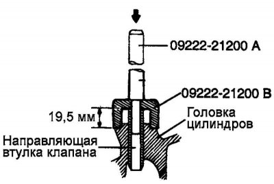
Fig. 2.134. Pressing out the old valve guide bushing
Using a special tool (mandrel for installing the guide bushing 09221-22000A), press out the old valve guide bushing from the cylinder head in the direction of the gasket surface (Fig. 2.134).
Ream the cylinder head bore to fit a valve guide bushing of the appropriate oversize (oversized diameter).
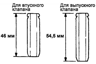
Fig. 2.135. Difference in length of guide bushings for intake and exhaust valves
Using a special tool (guide bushing installation mandrel 09221–22000B), press in a new valve guide bushing from the camshaft bed side. Note the difference in length between the intake and exhaust valve guide bushings (Fig. 2.135).
After installing the valve guide, insert the new valve and make sure the clearance between the guide and the valve stem is within the specified value.
After replacing the valve guide, check that the valve is seated correctly in the valve seat. If necessary, treat the valve seat.
Assembly
Install the valve spring seats.
Note: Clean all parts thoroughly before assembly. Apply engine oil to all moving and rotating parts.
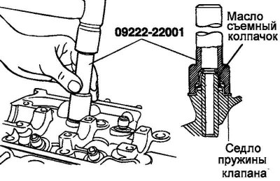
Fig. 2.136. Installing the oil seal
Using a special tool (mandrel for installing the oil seal 09222-22001), lightly install the oil seal into place (Fig. 2.136).
Note: Reusing valve stem seals is not permitted.
Note: Incorrect installation of the valve stem seal may result in oil leaks through the valve guide.
Lubricate the valve stem with engine oil. Insert the valve into the valve guide. Do not force the valve stem through the valve stem seal. After installing the valve, check for smooth movement.
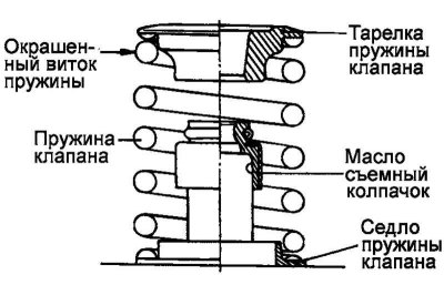
Fig. 2.137. Valve spring installation diagram
Install the valve spring so that the painted spring coil is located near the spring plate (top), and then install the valve spring plate (Fig. 2.137).
Using the special tool (valve spring compressor 09222-28000 and adapter 09222-28100), compress the valve spring and install the crackers. Before removing the special tool after installing the valve, check that the crackers are securely installed.
Note: When compressing the valve spring, make sure that the spring plate does not touch the valve stem seal.
Clean the mating surfaces under the gasket on the cylinder head and cylinder block.
Check that the cylinder head gasket identification marks match the technical data.
Install the cylinder head gasket onto the cylinder block with the identification mark facing up (towards the cylinder head).
Before installing the cylinder head bolts, measure their length.
Maximum bolt length: 99.4 mm.
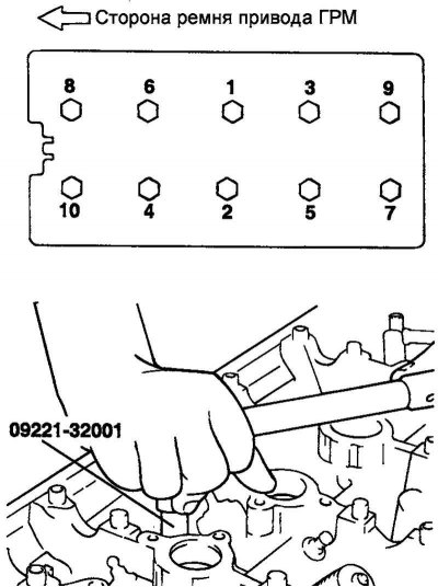
Fig. 2.138. Cylinder head bolt tightening sequence
Tighten the cylinder head mounting bolts to the specified torque in the order shown in Figure 2.138.
Tightening torque with replacement of head parts, block or head mounting bolts): 63 Nm + loosen all bolts + 20 Nm + 90°+90° Without replacement of parts: 20 Nm + 90°+90°.