


Engine fuel system Hyundai Santa Fe 2
Distributed fuel injection system
Fig. 2.363. Injector operation switching diagram General information The Multi-port Fuel Injection (MFI) system consists of sensors that evaluate the engine condition,...
Fig. 2.363. Injector operation switching diagram General information The Multi-port Fuel Injection (MFI) system consists of sensors that evaluate the engine condition,...

Troubleshooting the fuel injection control system
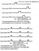
Output signal shape from the main sensors The output signal shapes from the main fuel system sensors are given. These include: CMP (camshaft position sensor), CKP...
Output signal shape from the main sensors The output signal shapes from the main fuel system sensors are given. These include: CMP (camshaft position sensor), CKP...

Distributed fuel injection control system
Fig. 2.367. Location of system components: 1 - Coolant Temperature Sensor (ECT); 2 – Air flow sensor and intake manifold air temperature sensor for the model with 2.4 I4...
Fig. 2.367. Location of system components: 1 - Coolant Temperature Sensor (ECT); 2 – Air flow sensor and intake manifold air temperature sensor for the model with 2.4 I4...

Fuel supply system
Fig. 2.389. Accelerator pedal (2.4 l engine) Fig. 2.390. Accelerator pedal (2.7 l engine) Removal the pedal Disconnect the bushing and accelerator pedal cable from the...
Fig. 2.389. Accelerator pedal (2.4 l engine) Fig. 2.390. Accelerator pedal (2.7 l engine) Removal the pedal Disconnect the bushing and accelerator pedal cable from the...

Removal, inspection and installation of fuel lines and fuel vapor discharge lines
Fig. 2.394. Components of fuel lines and fuel vapor discharge lines Removal Remove the fuel filler cap to relieve pressure in the tank. Raise the vehicle and disconnect...
Fig. 2.394. Components of fuel lines and fuel vapor discharge lines Removal Remove the fuel filler cap to relieve pressure in the tank. Raise the vehicle and disconnect...
Troubleshooting by diagnostic codes
Operating principle and purpose of diagnostic parameters The mass air flow (MAF) sensor is located in the air duct behind the air cleaner. The sensor measures the mass...
Operating principle and purpose of diagnostic parameters The mass air flow (MAF) sensor is located in the air duct behind the air cleaner. The sensor measures the mass...

Removal, checking and installation the positive crankcase ventilation valve
Fig. 2.348. Location of emission control system components (2.4 l engine): A – crankcase ventilation valve; B – electromagnetic valve for purging the adsorber; C –...
Fig. 2.348. Location of emission control system components (2.4 l engine): A – crankcase ventilation valve; B – electromagnetic valve for purging the adsorber; C –...
Fuel vapor recovery system
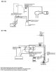
Fig. 2.354. Elements of the fuel vapor recovery system Fig. 2.355. Evaporative absorber purge solenoid valve Checking the purge solenoid valve of the adsorber Disconnect...
Fig. 2.354. Elements of the fuel vapor recovery system Fig. 2.355. Evaporative absorber purge solenoid valve Checking the purge solenoid valve of the adsorber Disconnect...
Emission Control System (Catalytic Converter Models)
The content of toxic components in exhaust gases (CO, CH, NOx) is limited by a combination of design features of the vehicle engine and special control elements in the...
The content of toxic components in exhaust gases (CO, CH, NOx) is limited by a combination of design features of the vehicle engine and special control elements in the...
Air-fuel ratio control system (MFI multipoint fuel injection system)
Using signals from the oxygen sensor, the Multiport Fuel Injection (MFI) system controls the timing and duration of the open state of the injector installed in the...
Using signals from the oxygen sensor, the Multiport Fuel Injection (MFI) system controls the timing and duration of the open state of the injector installed in the...
This section is available on russian, bulgarian, belarusian, ukrainian, serbian, croatian, romanian, polish, slovak, hungarian
We recommend other sections on the topic of Hyundai manuals:
Power unit: Fuel supply (carburetor) Hyundai Accent 1 (1994-1999)
Power unit: Fuel system Hyundai Elantra 2 (1995-2000, petrol)
Power unit: Fuel system Hyundai Getz (2002-2011)
Power unit: Fuel system Hyundai Sonata 3 (1993-1998)
Power unit: Fuel system (diesel) Hyundai Tucson 1 (2005-2010)
Power unit: Power and exhaust system Hyundai Matrix (2001-2010, petrol)
Link in different formats to this section
TextHTMLBB Code
- User manual
- Control devices
- Heating and ventilation
- Seat control
- Car driving
- Maintenance and care
- Vehicle Specifications
- Engine 2.0 and 2.4 liters
- Engine specifications
- Engine maintenance
- Engine repair
- Cooling system
- Intake and exhaust system
- Fuel system
- Engine 2.7 liter
- Engine maintenance
- Engine repair
- Cooling system
- Intake and exhaust system
- Transmission
- Transmission specifications
- Mechanical gearbox
- Automatic gearbox
- Drive shafts
- Chassis
- Suspension and wheels
- Steering
- Brake system
- Body
- Exterior (external elements)
- Electrical equipment
- Equipment and devices
- Power devices
- Specifications