
Contents: Checking the purge solenoid valve of…⇓ Data for verification ⇓ Checking the vacuum hose ⇓ Checking the adsorber ⇓ Checking the two-way valve ⇓ Checking the fuel filler cap ⇓
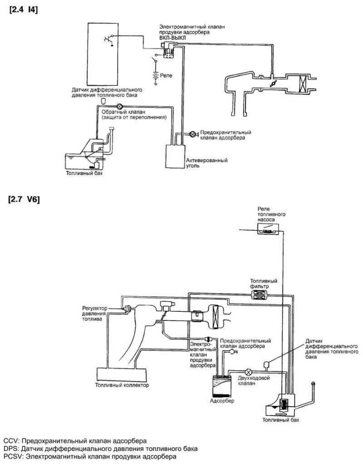
Fig. 2.354. Elements of the fuel vapor recovery system
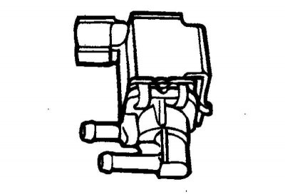
Fig. 2.355. Evaporative absorber purge solenoid valve
Checking the purge solenoid valve of the adsorber
Disconnect the vacuum hose (black with red stripe) from the solenoid valve.
Disconnect the solenoid valve connector.
Note: The purge solenoid valve is controlled by the engine control unit; at low coolant temperatures, as well as when the engine is idling, the valve is closed and the evaporating fuel does not enter the intake manifold receiver. However, when the engine is warm and the vehicle is in normal driving mode, the valve opens and fuel vapors enter the intake manifold receiver.
Note: When disconnecting vacuum hoses, always make alignment marks first so that the hoses are in their original positions when reconnected.
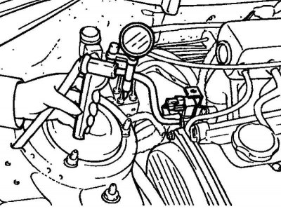
Fig. 2.356. Connecting a hand vacuum pump
Connect a hand vacuum pump to the solenoid valve nipple from which the vacuum hose with the red stripe was disconnected (Fig. 2.356).
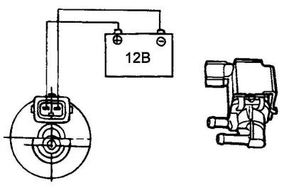
Fig. 2.357. Checking the purge solenoid valve of the adsorber
Create a vacuum with a vacuum pump and check the operation of the valve by connecting/disconnecting the power supply from the battery to the valve terminals (Fig. 2.357).
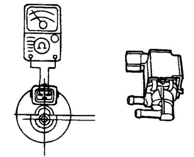
Fig. 2.358. Measuring current at the valve terminals
Measure the current at the terminals of the electromagnetic valve (Fig. 2.358).
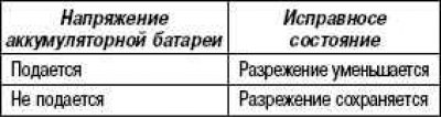
Data for verification
Winding (at 20°C): 0.45 A or less (at 12 V).
Winding resistance: 26 Ohm (at 20°C).
Checking the vacuum hose
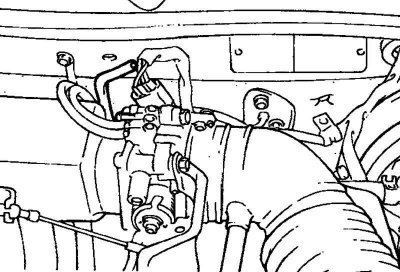
Fig. 2.359. Vacuum hose
Engine coolant temperature: 80–95°C.
Disconnect the vacuum hose from the fuel vapor recovery system fitting on the intake manifold and connect a hand vacuum pump to the fitting.
(Information is copied from the website hyundaibook)
Start the engine and check that as the engine speed increases, the vacuum remains almost constant.
Note: If vacuum is not created, there is likely deposits in the vacuum hose fitting bore (in the throttle body) and it needs to be cleaned.
Checking the adsorber
Check the condition of the CCV and its filter as shown in the figure.
Visually inspect the fuel vapor recovery system hoses for loose connections, damage, or sharp kinks.
Visually inspect the connections for any deformations, cracks or fuel leaks.
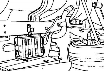
Fig. 2.360. Adsorber
Remove the adsorber and check it for cracks or damage (Fig. 2.360).
Checking the two-way valve
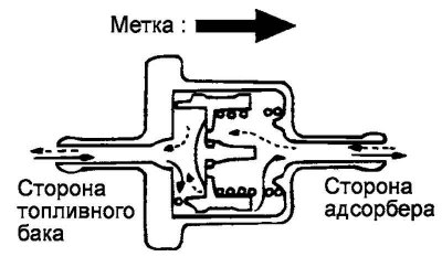
Fig. 2.361. Checking the two-way valve
Make sure that air flows through the valve in the direction shown in Figure 2.361.
When installing the valve, make sure it is correctly oriented according to the arrow marked on the valve body.
Checking the fuel filler cap
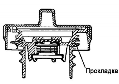
Fig. 2.362. Cover gasket
Check the condition of the O-ring gasket of the cover and the fuel filler cap for damage or deformation. If necessary, replace the filler cap (Fig. 2.362).