
Contents: Coolant Temperature Sensor (ECT…⇓ Checking with the HI-SCAN (PRO)…⇓ Testing with a multitester ⇓ Troubleshooting Guide ⇓ Installing the sensor ⇓ Mass Air Flow (MAF) Sensor and…⇓ Troubleshooting Tips ⇓ Air flow sensor (MAF 2.7 V6) ⇓ Troubleshooting Guide ⇓ Intake Manifold Air Temperature…⇓ Troubleshooting Guide ⇓ Checking the sensor ⇓ Throttle Position Sensor (TPS) ⇓ Checking the sensor ⇓ Checking with a voltmeter ⇓ Troubleshooting Guide ⇓ Idle Speed Control (ISA) Servo ⇓ Troubleshooting Guide ⇓ Oxygen sensor with heater (HO2S 2.4L) ⇓ Troubleshooting Guide ⇓ Checking the sensor ⇓ Nominal value ⇓ Oxygen sensor with heater (HO2S 2.7L) ⇓ Troubleshooting Guide ⇓ Checking with a voltmeter ⇓ Camshaft Position Sensor ⇓ Troubleshooting Guide ⇓ Crankshaft position sensor ⇓ Troubleshooting Guide ⇓ Nozzles ⇓ Checking the injectors ⇓ Troubleshooting Guide ⇓ Injectors (2.7 V6) ⇓ Checking the injectors ⇓ Checking the injector with a…⇓ Checking the resistance between the…⇓ Evaporative Evaporative Canister…⇓ Knock sensor ⇓ Troubleshooting Guide ⇓ Checking the sensor ⇓ Power steering hydraulic fluid…⇓ Replacing the fuel level sensor and…⇓ Checking the operation of the fuel…⇓ Checking the vacuum channel of the…⇓ Checking fuel pressure ⇓ Cleaning the throttle valve ⇓
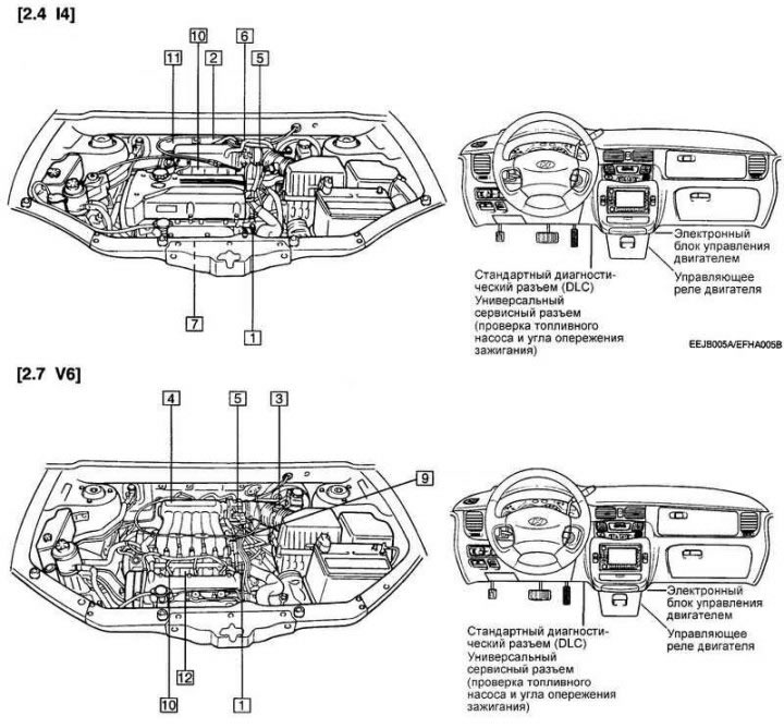
Fig. 2.367. Location of system components: 1 - Coolant Temperature Sensor (ECT); 2 – Air flow sensor and intake manifold air temperature sensor for the model with 2.4 I4 engine; 3 – Air flow sensor for the model with 2.7 V6 engine; 4 – Intake manifold air temperature (IAT) sensor for the model with 2.7 V6 engine; 5 – Throttle position sensor (TPS); 6 – idle speed control servo (ISA); 7 – Oxygen sensor with heater (HO2S); 8 – camshaft position sensor (CMP); 9 – crankshaft position sensor (CSP); 10 – nozzle; 11 – purge solenoid valve (PCSV); 12 – knock sensor (KS); 13 – power steering hydraulic system fluid pressure switch.
Coolant Temperature Sensor (ECT SENSOR)
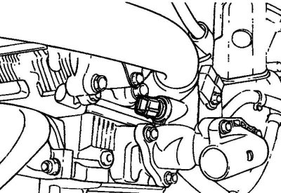
Fig. 2.368. Coolant temperature sensor
The coolant temperature sensor is installed in the cooling jacket channel of the cylinder head. It determines the temperature of the engine coolant and transmits a signal to the electronic engine control unit. The sensor is a thermistor sensitive to temperature changes. The resistance of the sensor decreases as the temperature of the engine coolant increases. Based on the voltage of the sensor signal, the electronic engine control unit evaluates the temperature of the coolant and ensures enrichment of the air-fuel mixture during engine warm-up.
Checking with the HI-SCAN (PRO) tester
The data for testing using the HI-SCAN (PRO) tester is presented in table 2.32.
Testing with a multitester
Remove the coolant temperature sensor from the engine intake manifold.

Fig. 2.369. Measuring the resistance between the sensor terminals
Immerse the measuring part of the sensor in water with a known temperature and measure the resistance between the sensor terminals (Fig. 2.369).
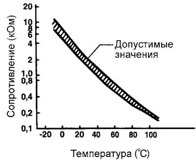
Fig. 2.370. Diagram of acceptable values
If the measured resistance differs from the nominal values, replace the coolant temperature sensor (Fig. 2.370).

Troubleshooting Guide
If the idle speed during warming up of a cold engine does not correspond to the norm, or warming up of the engine is accompanied by black smoke from the exhaust pipe, then most likely the cause of this may be the coolant temperature sensor.
Installing the sensor
Apply the specified sealant to the threaded portion of the sensor.
Recommended sealant: LOCTITE 962T or equivalent.
Install the sensor in place and tighten it to the specified torque.
Tightening torque of the coolant temperature sensor: 15–20 N·m.
Connect the sensor connector securely.
Mass Air Flow (MAF) Sensor and Manifold Air Temperature (IAT) Sensor
The film type sensor consists of a heat-sensitive film, a housing and a measurement zone (hybrid type). The principle of measuring air flow by a sensor of this type is based on the change in heat transfer from the surface of the film to the flow of air flowing through the sensor.
The air flow sensor produces oscillatory pulses (open-closed) in the 5 V range, which are supplied by the electronic engine control unit.
Intake manifold air temperature (IAT) sensor, located in the intake manifold, resistor type; it measures the air temperature. Information about the temperature state of the air in the intake manifold allows the electronic engine control unit to measure the optimal amount of fuel injected into the engine through the injectors with greater accuracy.
Troubleshooting Tips
If the engine suddenly stalls, restart it and then move the MAF sensor wiring harness. If the engine stalls in this case, check for contact at the MAF sensor connector.
If the output voltage at the MAF sensor is not "0" with the ignition on (the engine is not running), check the condition of the MAF sensor itself or the engine control module (PCM).
If the engine idles even though the sensor output voltage is not normal, check the following:
- Possibility of changing the direction of air flow in the intake manifold, disconnection of the air pipe, clogging of the air filter. Incomplete combustion of fuel in the combustion chamber, malfunction of spark plugs, ignition coil, injectors or their incorrect interaction.
- If there are no signs of a faulty MAF sensor, check that it is installed correctly.
Note: If the car is new (its mileage is less than 500 km), the readings of the mass air flow sensor are 10% higher than the actual air flow.
Note: It is recommended to use a digital voltmeter when performing tests.
Note: Before starting the test, it is necessary to warm up the engine to a coolant temperature of 80–90°C.
Air flow sensor (MAF 2.7 V6)
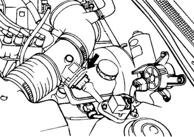
Fig. 2.371. Air flow sensor
The film type sensor consists of a heat-sensitive film, a housing and a measurement zone (hybrid type). The principle of measuring air flow by a sensor of this type is based on the change in heat transfer from the surface of the film to the flow of air flowing through the sensor. The air flow sensor produces oscillatory pulses (break-short circuit) in the range of 5 V (see table 2.35), which are supplied from the electronic engine control unit.
Troubleshooting Guide
If the engine suddenly stalls, restart it and then move the MAF sensor wiring harness. If the engine stalls in this case, check for contact at the MAF sensor connector.
If the output voltage at the MAF sensor is not "0" with the ignition on (the engine is not running), check the condition of the MAF sensor itself or the engine control module (PCM).
If the engine idles even though the sensor output voltage is not normal, check the following:
- Possibility of changing the direction of air flow in the intake manifold, disconnection of the air pipe, clogging of the air filter.
- Incomplete combustion of fuel in the combustion chamber, malfunction of spark plugs, ignition coil, injectors or their incorrect interaction.
- If there are no signs of a faulty MAF sensor, check that it is installed correctly.
Note: If the car is new (its mileage is less than 500 km), the readings of the mass air flow sensor are 10% higher than the actual air flow.
Note: It is recommended to use a digital voltmeter when performing tests.
Note: Before starting the test, it is necessary to warm up the engine to a coolant temperature of 80–90°C.
Intake Manifold Air Temperature Sensor (IAT SENSOR)
The intake manifold air temperature sensor is integrated into the manifold absolute pressure (MAP) sensor. The sensor is a resistor that changes the signal voltage depending on the temperature of the air entering the intake manifold.
In accordance with the signal from the intake manifold air temperature sensor, the engine control unit will adjust the required fuel supply (basic fuel injector open time).
Troubleshooting Guide
Under the following conditions, the engine malfunction indicator lamp lights up and the corresponding malfunction code is output to the HI-SCAN (PRO) tester.
When the air temperature in the intake manifold registered by the sensor is below –40°C or above 120°C.
When the input signal from the intake manifold air temperature sensor is below 0.1 V or above 4.8 V when the engine is warm.
Checking the sensor
Use a multimeter to measure the sensor output voltage
Measure the voltage between terminals 1 and 2 of the intake manifold air temperature (IAT) sensor
If the voltage is significantly different from the specified value, replace the intake manifold air temperature (IAT) sensor assembly.
Throttle Position Sensor (TPS)
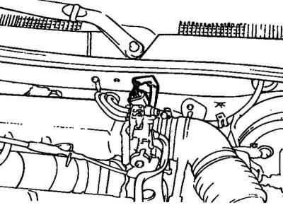
Fig. 2.372. Throttle position sensor
The throttle position sensor is a potentiometer with a sliding contact that moves according to the rotation of the throttle axis, indicating the opening angle of the valve. When the throttle axis rotates, the signal voltage of the throttle position sensor changes and, based on the change in the value of the sensor signal voltage and the rate of its change, the electronic engine control unit determines the degree and speed of opening of the throttle valve.
Checking the sensor
The data for testing using the HI-SCAN (PRO) tester is presented in table 2.38.
Checking with a voltmeter
Disconnect the throttle position sensor connector.
For the 2.4 I4 engine model, measure the resistance between pin 1 (sensor ground) and pin 2 (sensor power supply), and for the 2.7 V6 engine model, between pin 2 (sensor ground) and pin 1 (sensor power supply).
Nominal value: 3.5–6.5 kOhm.
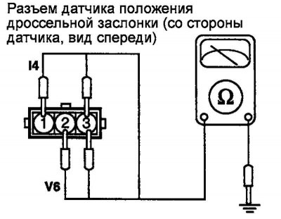
Fig. 2.373. Connecting an ohmmeter
Connect an analog type ohmmeter to terminal 1 (sensor ground) and terminal 3 (sensor signal) of the throttle position sensor for the 2.4 I4 model and to terminal 2 (sensor ground) and terminal 3 (sensor signal) for the 2.7 V6 model (Fig. 2.373).
Slowly open the throttle valve from fully closed (idle) to fully open position, check that the resistance changes smoothly in proportion to the throttle opening angle.
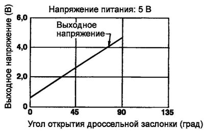
Fig. 2.374. Output voltage diagram
If the resistance either differs from the nominal value or does not change smoothly, replace the throttle position sensor.
Tightening torque of the throttle position sensor: 1.5–2.5 N·m.
Troubleshooting Guide
The throttle position sensor signal is more important for the automatic transmission control system than for the engine control system. If the throttle position sensor is faulty, then "shock" (jerky) gear shifting occurs and other malfunctions may occur.
Idle Speed Control (ISA) Servo
The idle speed control servo drive is an electric motor with two windings, which are switched on by separate control circuits of the electronic engine control unit.
Depending on the duty cycle of the pulse period ("pulse duty factor") the difference in magnetic forces of the two windings will rotate the electric motor shaft by a certain angle, thus changing the flow section of the bypass channel. The bypass channel is located in the throttle body parallel to the throttle channel in the place where the idle speed regulator servo is installed.
Troubleshooting Guide
The engine malfunction indicator lamp lights up or the HI-SCAN (Pro) tester displays the corresponding malfunction code when the condition below is met (see table 2.39).
When the primary voltage circuit in the PCM is either open or short circuited.
When the ignition system control by the PCM is disrupted.
An open or short circuit in the idle speed control servo circuit can be detected immediately after the ignition is turned on.
Oxygen sensor with heater (HO2S 2.4L)
The oxygen sensor determines the concentration of oxygen in the exhaust gases and accordingly changes the voltage of the signal that is sent to the electronic engine control unit.
If the air-fuel mixture is richer than the stoichiometric ratio (i.e. if the oxygen concentration in the exhaust gases is low), the sensor signal voltage is approximately 1 V. If the air-fuel mixture is poorer than the stoichiometric ratio (i.e. if the oxygen concentration in the exhaust gases is high), the sensor signal voltage is approximately 0 V. Based on this signal, the electronic engine control unit regulates the fuel supply so that the air-fuel mixture is as close as possible to the stoichiometric ratio. The oxygen sensor (zirconium) is equipped with a heater, which ensures stable operation of the sensor in all modes.
Troubleshooting Guide
If the oxygen sensor is faulty, the exhaust gases will contain an increased content of toxic substances.
If the oxygen sensor signal (output voltage) differs from the nominal value, after the test showed the sensor to be in good condition, then the cause of the malfunction is in the components of the air-fuel mixture control system:
- injector malfunction;
- air enters the intake manifold through a damaged gasket;
- malfunction of the manifold absolute pressure (MAP) sensor, air flow sensor, intake manifold air temperature sensor and coolant temperature sensor.
Checking the sensor
Replace the oxygen sensor if it is faulty.
Apply battery voltage to terminals 3 and 4.
Note: Before checking, warm up the engine until the coolant temperature reaches 80–95°C.
Note: Please use a high-precision digital voltmeter when taking measurements.
Note: Disconnect the oxygen sensor connector and measure the resistance between terminal 3 and terminal 4.
Nominal value
Note: Be careful when performing this operation. Accidentally applying voltage to terminals 1 and 2 will damage the oxygen sensor.
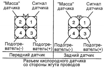
Fig. 2.375. Connection diagram of the sensor connector to the voltmeter
Connect a high resistance digital voltmeter between terminals 1 and 2 (Fig. 2.375).
While successively accelerating the engine, measure the output voltage of the oxygen sensor.
If there are any deviations, the oxygen sensor may be faulty.
Tightening torque of the oxygen sensor: 50–60 Nm.
Oxygen sensor with heater (HO2S 2.7L)
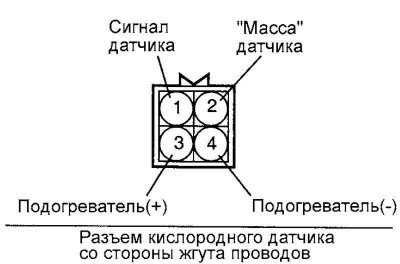
Fig. 2.376. Oxygen sensor connector on the wiring harness side
The oxygen sensor determines the concentration of oxygen in the exhaust gases and accordingly changes the voltage of the signal that goes to the electronic engine control unit. If the composition of the air-fuel mixture is richer than the stoichiometric ratio (i.e. if the concentration of oxygen in the exhaust gases is small), then the voltage of the sensor signal is approximately 0 V.
If the air-fuel mixture is poorer than the stoichiometric ratio (i.e. if the concentration of oxygen in the exhaust gases is high), then the sensor signal voltage is approximately 5 V. Based on this signal, the electronic engine control unit regulates the fuel supply so that the composition of the air-fuel mixture is as close as possible to the stoichiometric ratio. The oxygen sensor is equipped with a heater, which ensures stable operation of the sensor in all modes.
Troubleshooting Guide
If the oxygen sensor is faulty, the exhaust gases will contain an increased content of toxic substances.
If the oxygen sensor signal (output voltage) differs from the nominal value, after the test showed the sensor to be in good condition, then the cause of the malfunction is in the components of the air-fuel mixture control system:
- injector malfunction;
- air enters the intake manifold through a damaged gasket;
- malfunction of the air flow sensor, intake manifold air temperature sensor and coolant temperature sensor.
Checking with a voltmeter
Disconnect the oxygen sensor connector and measure the resistance between terminals 3 and 4.
Note: Before checking, warm up the engine until the coolant temperature reaches 80–95°C.
Note: Be especially careful when performing this test. If the connections are incorrect or if the terminals are shorted together, the oxygen sensor will fail.
Connect a high impedance digital voltmeter between pins 1 and 2.
After revving the engine several times, measure the output voltage of the oxygen sensor.
The presence of deviations in the readings may indicate a faulty oxygen sensor.
Tightening torque of the oxygen sensor: 40–50 Nm.
Camshaft Position Sensor
The operating principle of the camshaft position sensor is based on the Hall effect. The sensor determines the moment when the pistons of cylinders No.1 and No.4 reach the top dead center on the compression stroke.
Based on the sensor signal, the electronic engine control unit determines the sequence of fuel injection for individual cylinders.
Troubleshooting Guide
If the camshaft position sensor is unstable, the consequence may be a violation of the fuel injection sequence in the cylinders, and this, in turn, leads either to the engine stalling, or to its unstable operation at idle, or to the impossibility of its normal acceleration.
Crankshaft position sensor
The crankshaft position sensor (CPS) uses the Hall effect to detect the position of the crankshaft (piston position), then convert it into a signal and send this signal to the electronic engine control module (PCM). Based on this input signal, the PCM controls the timing of fuel injection into the cylinders and the ignition timing.
Troubleshooting Guide
If you experience unexpected knocks (knocks) while driving or if the engine suddenly stalls, try moving the crankshaft position sensor wiring harness. If this causes the engine to stall, check the reliability of the contact in the connector.
If the tachometer shows 0 min⁻¹ when cranking the engine with the starter, check the engine crankshaft position sensor, timing belt or ignition system.
If the engine is idling but the crankshaft position sensor readings are not normal, check the following:
- coolant temperature sensor is faulty;
- idle speed control servo drive is faulty;
- incorrect adjustment of engine idle speed.
The engine can run without a signal from the crankshaft position sensor, but restarting the engine is not possible. Once the sensor detects the TDC position, this data is stored until the next engine start.
Nozzles
The injectors inject fuel into the engine cylinders based on a signal coming from the electronic engine control unit. The amount of fuel supplied by the injector is determined by the time during which a control pulse is supplied to the injector winding (the open state time of the injector needle valve). The duration of the electromagnetic valve activation, in turn, is determined by the duration of the signal pulse coming from the electronic engine control unit.
Checking the injectors
The data for testing using the HI-SCAN (PRO) tester is presented in table 2.45.
Note: The presence of an injector control pulse is determined by the battery charge (not lower than 11 V) at engine starting speeds not exceeding 250 min⁻¹.
If the coolant temperature is below 0°C, the engine control unit (PCM) ensures simultaneous fuel injection into all cylinders.
If the car is new (its mileage is no more than 500 km), the duration of the injector control pulse is approximately 10% greater than the nominal value.
Troubleshooting Guide
If you have difficulty starting a warm engine, check for low pressure in the fuel lines and the tightness of the injectors.
If the engine does not start and the injectors do not work when the crankshaft is turned by the starter, then check for the following faults (not related to the injectors).
Malfunction of the power supply circuit of the electronic engine control unit or the ground connection circuit.
Malfunction of the engine control relay and fuel pump relay.
Crankshaft position sensor and camshaft position sensor malfunction.
If after disabling the injector of one of the cylinders there is no change in the engine operation at idle speed, then perform the following checks for this cylinder.
Check the injector and its wiring harness.
Check the spark plug and spark plug wire.
Check the compression.
If the injector operating time (injector opening signal duration) differs from the nominal value, even if the test showed that the injector and its wiring harness are in good condition, perform the following checks.
Incomplete combustion in one of the cylinders. (Spark plug, ignition coil malfunction, lack of compression, etc.)
The valve is not sealed properly in the seat of the exhaust gas recirculation (EGR) system
Injectors (2.7 V6)
The injectors inject fuel into the engine cylinders based on a signal coming from the electronic engine control unit. The amount of fuel supplied by the injector is determined by the time during which a control pulse is supplied to the injector winding (the open state time of the injector needle valve). The duration of the electromagnetic valve activation, in turn, is determined by the duration of the signal pulse coming from the electronic engine control unit.
Checking the injectors
The data for testing using the HI-SCAN (PRO) tester is presented in table 2.47.
Note: The presence of an injector control pulse is determined by the battery charge (not lower than 11 V) at engine starting speeds not exceeding 250 min⁻¹.
If the coolant temperature is below 0°C, the engine control unit (PCM) ensures simultaneous fuel injection into all cylinders.
If the car is new (its mileage is no more than 500 km), the duration of the injector control pulse is approximately 10% greater than the nominal value.
Checking the injector with a phonendoscope and voltmeter. Checking the sound of the working injector
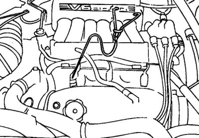
Fig. 2.377. Checking the injector using a phonendoscope
Using a phonendoscope, check the operation of the injector (the presence of characteristic creaking sounds) when the engine is idling. Check that as the engine crankshaft speed increases, the injector's operating frequency also increases.
Note: Do not confuse the sound of the injector being tested with the sound of the adjacent injector being tested, transmitted through the fuel rail, especially if the injector being tested is not working.
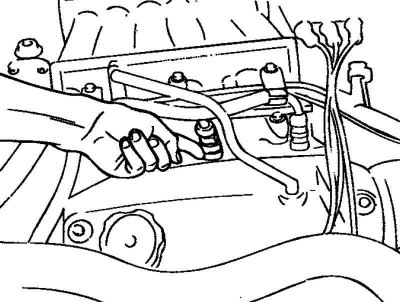
Fig. 2.378. Checking the injector by touch with your finger
If a phonendoscope is not available, then check the operation of the injector by touch with your finger. If vibrations from the operation of the injector are not felt, then check the wiring harness connector, the injector, or the presence of a control pulse from the electronic engine control unit (Fig. 2.378).
Checking the resistance between the terminals (resistance of the injector solenoid valve winding)
Disconnect the connector of the injector being tested.
Measure the resistance between the connector terminals.
Nominal value: 13-16 Ohm at 20°C.
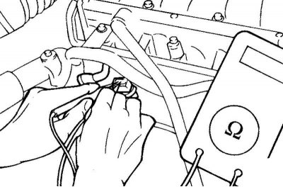
Fig. 2.379. Connecting the injector connector
Securely connect the injector connector (Fig. 2.379).
Evaporative Evaporative Canister Purge Solenoid Valve
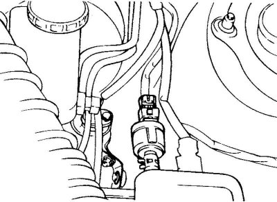
Fig. 2.380. Evaporative absorber purge solenoid valve
The purge solenoid valve operates in pulse-width mode to control the air flow to purge the fuel vapor recovery system's purge canister.
Knock sensor
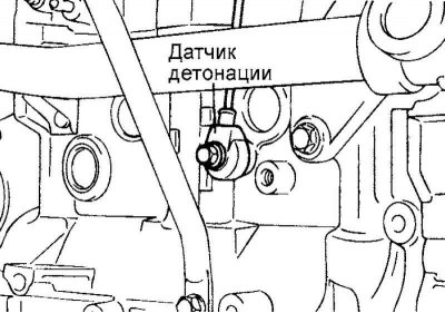
Fig. 2.381. Tetonation sensor
The knock sensor (piezoelectric) is installed on the cylinder block wall to detect detonation combustion of fuel in the engine cylinders. Vibration of the cylinder block caused by detonation creates pressure acting on the piezoelectric crystal in the sensor. As a result, the vibration is converted into a signal (voltage) proportional to its intensity, which is transmitted to the electronic engine control unit. If detonation occurs in the engine, the electronic engine control unit reduces the ignition timing until it disappears.
Troubleshooting Guide
The engine malfunction indicator lamp lights up or the HI-SCAN (Pro) tester displays the corresponding malfunction code under the condition indicated below.
The knock sensor signal is not detected, even when the engine is overloaded.
When the knock sensor signal is below normal.
Checking the sensor
Disconnect the knock sensor connector.
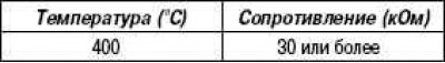
Measure the resistance between pins 2 and 3 of the connector.
Nominal value: approximately 5 MΩ at 20°C.
If the resistance is zero, replace the knock sensor.
Knock sensor tightening torque: 16–28 Nm.
Measure the electrical capacitance of the sensor between terminals 2 and 3 of the connector.
Nominal value: 800–1600 pF.
Power steering hydraulic fluid pressure switch
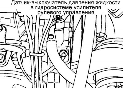
Fig. 2.382. Power steering hydraulic system fluid pressure switch
The power steering pressure switch senses the steering load and transmits it as an electrical signal to the engine control module (ECM). The ECM, in turn, adjusts the idle speed control servo to compensate for the decrease in idle speed caused by the power steering pump load.
Replacing the fuel level sensor and fuel filter
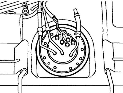
Fig. 2.383. Fuel filter and sensor
Remove the fuel tank filler cap to relieve pressure in the fuel lines.
Jack up the vehicle, disconnect the connector from the fuel pump, then disconnect the feed line and fuel return line from the fuel pump.
Remove the fuel pump mounting screws and remove the fuel pump assembly from the fuel tank.
Remove the fuel level sensor and fuel filter from the fuel pump.
Check and replace if necessary.
Checking the operation of the fuel pump
Turn the ignition key to the OFF position.
Apply battery voltage to the fuel pump terminals to check its functionality.
Note: The fuel pump is located inside the fuel tank, so its functionality can be determined by the characteristic sound coming from the fuel tank when the fuel pump is turned on, without removing the filler cap.
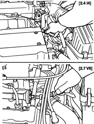
Fig. 2.384. Checking the fuel pump
Pinch the fuel hose with your fingers to feel the fuel pulsation when the fuel pump is running (Fig. 2.384).
Checking the vacuum channel of the fuel vapor removal system
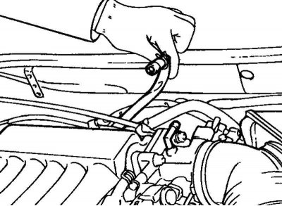
Fig. 2.385. Disconnecting the vacuum hose
Disconnect the vacuum hose from the fuel vapor removal system fitting on the throttle body and connect the vacuum pump (Fig. 2.385).
Start the engine and check that as the engine speed increases, the vacuum increases steadily.
Note: No vacuum means the vacuum passage in the throttle body is clogged and needs to be cleaned.
Checking fuel pressure
Reduce internal pressure in the fuel system and hoses:
- disconnect the fuel pump connector from the wiring harness side;
- start the engine and after it stalls, turn off the ignition;
- disconnect the negative battery terminal;
- connect the fuel pump connector from the wiring harness side.
Disconnect the fuel line from the fuel rail.
Caution: Due to residual pressure in the high-pressure fuel line, cover the connection point of the hose to the fuel manifold with a rag to prevent fuel from splashing.
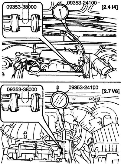
Fig. 2.386. Connecting the pressure gauge to the fuel manifold
Assemble the pressure measuring unit (adapter and measuring device) and connect it to the fuel pipe and fuel manifold. Secure the assembled parts with the nominal pressure (Fig. 2.386).
Tightening torque of the pressure gauge to the fuel manifold: 25–35 N·m.
Connect the negative terminal to the battery.
Apply battery voltage to the fuel pump service terminal and activate the fuel pump. As the fuel pressure in the system increases, check for fuel leaks at the connections.
Start the engine and let it idle.
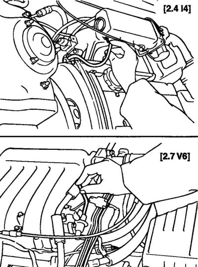
Fig. 2.387. Disconnecting the vacuum hose from the pressure regulator
Disconnect the vacuum hose from the pressure regulator and plug the hose. Measure the fuel pressure in the system with the engine idling (Fig. 2.387).
Nominal value: 320–340 kPa.
Measure the fuel pressure with the vacuum hose connected to the fuel pressure regulator.
Nominal value: approximately 255 kPa.
If the above operations and measurements do not correspond to the nominal values, use the table below to try to determine the possible cause of the malfunction and perform the necessary repair work.
Stop the engine and observe the change in pressure in the fuel system. The pressure should remain constant for the first 5 minutes. If the fuel pressure drops, pay attention to the rate of pressure drop. Determine the possible malfunction according to the table below and eliminate the malfunction.
Reduce the fuel pressure in the system.
Disconnect the hose and remove the pressure gauge.
Caution: Due to residual pressure in the high-pressure fuel line, cover the connection point of the hose to the fuel manifold with a rag to prevent fuel from splashing.
Replace the fuel hose end O-ring.
Connect the fuel hose to the fuel rail and tighten to the specified torque.
Check for fuel leaks.
Cleaning the throttle valve
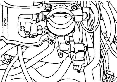
Fig. 2.388. Throttle assembly
Warm up the engine, then turn it off.
Note: Disconnect the intake manifold from the throttle body, check for dirt on the throttle body itself. Spray solvent from an aerosol can on the throttle body to remove dirt.
Disconnect the intake pipe from the throttle body.
Plug the bypass hole in the throttle body.
Note: Do not allow solvent to enter the bypass channel.
Spray the throttle valve with solvent from an aerosol can to remove dirt. Wait about 5 minutes for the solvent to soak the dirt. Then open the throttle valve and wipe the soaked dirt dry with a clean rag.
Caution: When spraying solvent, keep the throttle valve closed to prevent solvent from entering the intake manifold.
Start the engine, rev it up a few times and let it idle for about 1 minute.
Repeat the previous two operations again.
Clear the bypass hole.
Connect the inlet pipe.
Disconnect the (–) terminal from the battery for at least 10 s.