
Note: Due to the large number of modifications of MPI fuel injection systems installed on vehicles, this chapter provides information that applies to all vehicles in which this system is installed. We recommend that more thorough inspection and repair of system elements be carried out in specialized service centers.
The MPI fuel injection system operates using several components and parts: a fuel pump, which is located in the fuel tank, pumps fuel from it and delivers it through the fuel filter along the distribution line to the injection valves (injectors). The injection valves are controlled by a control unit, which calculates the injection moment and the amount of fuel injected. When current flows through the electromagnet winding, the injection valve needle is pulled in and fuel is injected (when the current circuit is broken, the spring returns the needle and the valve closes). The injection valves are controlled separately in the ignition sequence. The pressure regulator, located on the distribution line, maintains constant pressure in the fuel system.
The sucked air is cleaned in the air filter, in the body of which is located an air mass meter, which transmits information to the control unit. Pulse signals from other sensors, such as the atmospheric pressure meter or intake air temperature sensor, also arrive there.
Cleaned air is supplied to the engine through the intake manifold.
Lambda probe (oxygen sensor) serves to measure the oxygen content in the exhaust gases and transmit information to the control unit in the form of voltage.
The throttle body contains a throttle valve, which regulates the amount of air via the gas pedal. The throttle body also contains an idle speed adjustment mechanism that regulates the air supply bypassing the throttle valve. The idle speed controller is equipped with an idle speed sensor and an idle speed switch.
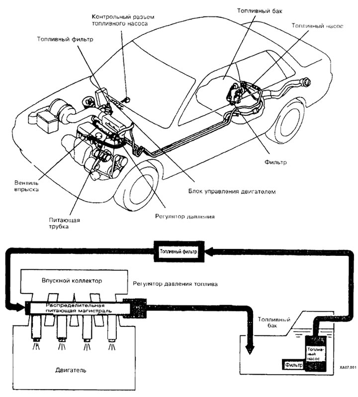
MPI fuel injection system layout diagram
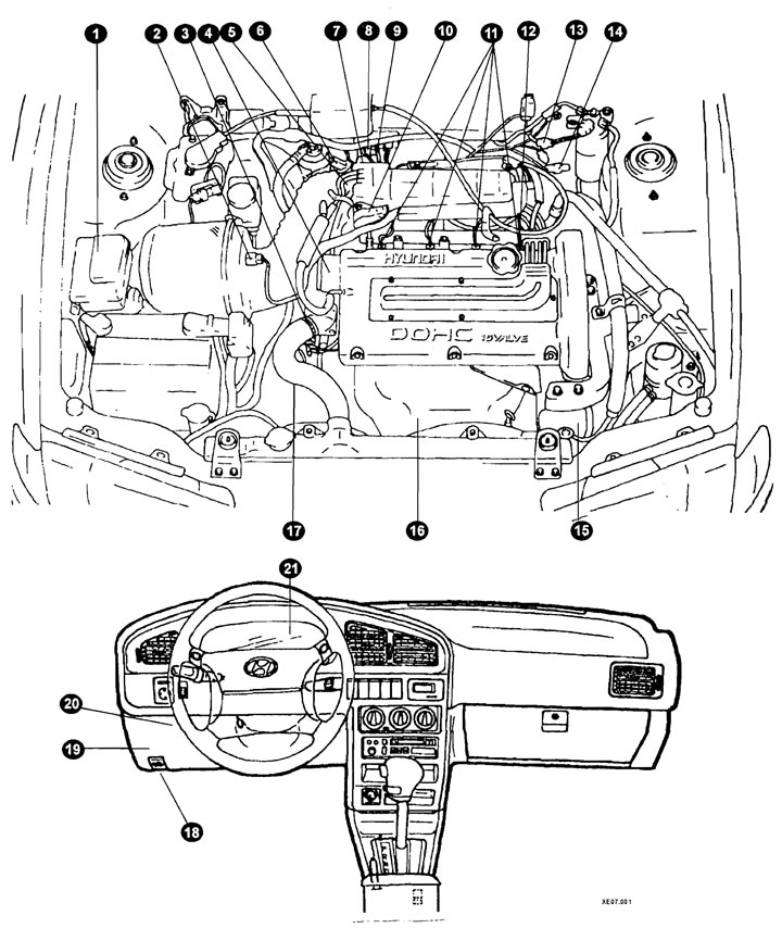
Location of fuel injection system components on a vehicle
1 - air conditioning system relay;
2 - air flow sensor;
3 - coolant temperature sensor;
4 - crankshaft position sensor;
3 - servomotor (ISC);
6 - start inhibit switch;
7 - temperature sensor;
8 - fuel tank ventilation electromagnetic valve;
9 - solenoid valve (version of execution);
10 - camshaft position sensor;
11 - nozzle (injection valve);
12 - ignition system transistor;
13 - ignition timing adjustment output;
14 - Fuel pump check output;
15 - fuel pressure control relay;
16 - oxygen sensor;
17 - transmission selector;
18 - Self-diagnostic system plug;
19 - Engine control module relay;
20 - Engine Control Module (MPI);
21 - vehicle speed sensor (indicator).
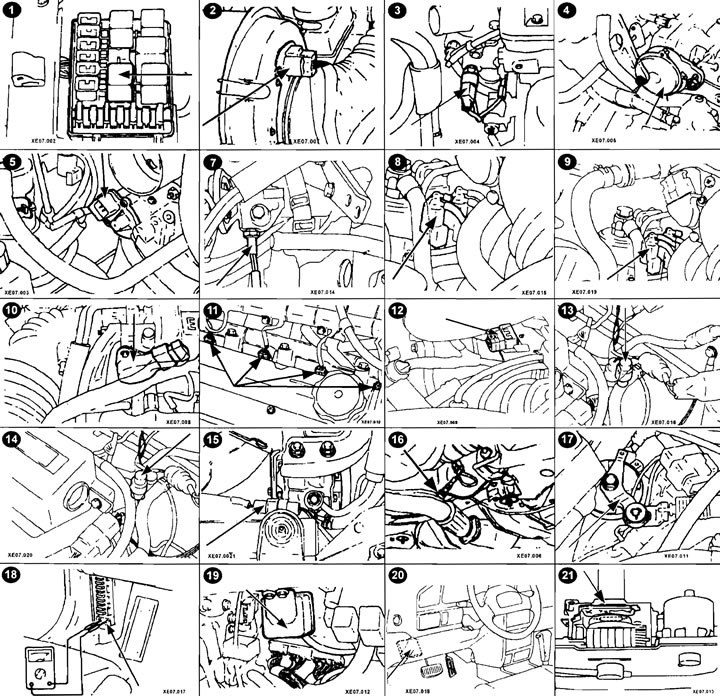
Location of injection system components on a vehicle
(The original can be read on the resource www.HyundaiBook.ru)