Contents: Malfunction indicator lamp ⇓ Self-diagnosis ⇓ Verification operation (using a…⇓ Test operation (using a voltmeter) ⇓
The following situations should be taken into account:
- 1. The engine starts with difficulty or does not start at all
- 2. Unstable idle speed
- 3. The engine does not develop full power.
If any of these faults occur, first perform the self-diagnosis check, then the basic engine check operations (correct engine adjustment, ignition system, etc.), and then check the system components with a scan tool.
Note:
- 1) Before removing or installing any part, read the diagnostic trouble code and then disconnect the negative battery terminal.
- 2) Before disconnecting the battery terminal, turn the ignition switch to the "OFF" position. Removing or connecting the battery drive while the engine is running with the ignition switch in the "OFF" position may cause damage to the engine control module (ECM).
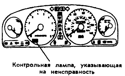
Malfunction indicator lamp
The malfunction indicator lamp is designed to notify the driver of a defect in the exhaust gas cleaning system. After the normal state has been reached, the lamp goes out. After the ignition switch is turned on, the lamp lights up and remains lit for 5 seconds.
Objects indicated by the control lamp:
- Heated oxygen sensor (HO2D)
- Air Flow Sensor (VAF)
- Intake Air Temperature (IAT) Sensor
- Throttle Position (TP) Sensor
- Engine Coolant Temperature (ECT) Sensor
- Crankshaft position sensor (CPS)
- Camshaft position sensor (CMP)
- Nozzles
- Fuel pump
- Exhaust Gas Recirculation Temperature Sensor
- Vehicle speed sensor
- Barometric pressure sensor
- Ignition coil.
Self-diagnosis
The engine control module monitors input/output signals (some signals continuously, others under specific conditions).
In this case, the MUD detects any malfunction entered into the diagnostic trouble code memory and sends a signal to the self-diagnostic output of 15 objects. The diagnostic results can be read using a voltmeter or a scanning device.
Diagnostic trouble codes reside in the module as long as the battery is operating. If the battery terminal or connector is disconnected, this will clear the trouble codes.
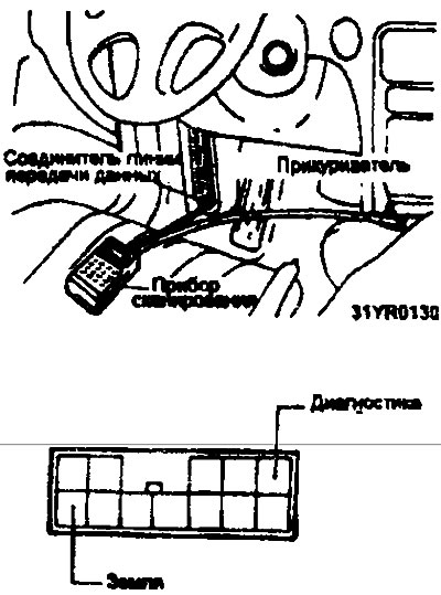
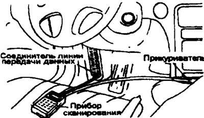
Verification operation (using a scanning device)
1. Turn the ignition switch to the off position.
2. Connect the scanning device to the connector in the fuse box.
3. Connect the power supply lead of the scanning device to the cigarette lighter.
4. Turn the ignition switch to the on position.
5. Use the scan tool to check diagnostic trouble codes.
6. Repair the faulty part based on the diagnostic chart.
7. Clear the diagnostic trouble code.
8. Disconnect the scanning device.
Test operation (using a voltmeter)
1. Connect the voltmeter to the data line connector.
2. Turn on the ignition switch, and the data from the MUD memory will start to be displayed.
After recording the defective object, check and repair it according to the "diagnostic card".
3. After the defective part is repaired, disconnect the negative battery terminal for 15 seconds or more and reconnect it to ensure that the diagnostic trouble code is cleared.