
Contents: General information ⇓ Fuel supply control ⇓ Engine Idle Speed Control ⇓ Ignition timing control ⇓ Fuel pump control ⇓ Fan relay control ⇓ Diagnostic mode ⇓ Instructions for checking for blown…⇓ Checking the distributed fuel…⇓ Diagnostic operations on the car ⇓ Malfunction Indicator Lamp (MIL) ⇓ Verification ⇓ Self-diagnosis ⇓ Test procedure (self-diagnosis) ⇓ Testing procedure (using a GST type…⇓
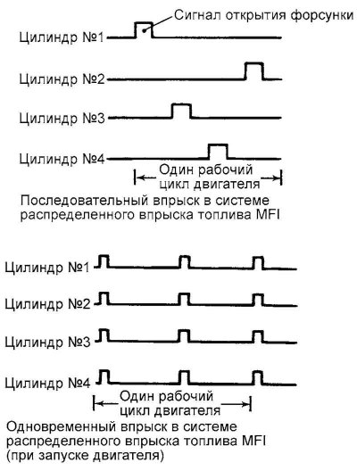
Fig. 2.363. Injector operation switching diagram
General information
The Multi-port Fuel Injection (MFI) system consists of sensors that evaluate the engine condition, an electronic engine control unit (ECM), which in turn controls the entire system based on the information received from the sensors and actuators, which are triggered by commands from the ECM. The ECM controls the fuel supply to the engine cylinders, the air flow at all idle speeds and the ignition timing. Moreover, the ECM has several self-diagnostic modes that facilitate troubleshooting when they occur.
Fuel supply control
The duration of the injector control pulse and the ignition advance angle are selected in such a way as to ensure the optimum air-fuel ratio of the mixture composition under constantly changing engine operating conditions. The intake port of each cylinder has one injector. Fuel is supplied by the fuel pump under pressure to the fuel manifold. To maintain the required pressure in the system, a pressure regulator is provided. Fuel is supplied to the injectors under pressure. Such a fuel supply system is called distributed. Typically, fuel is injected by the injector once every two crankshaft revolutions. The electronic engine control unit enriches the mixture composition in the "no feedback" mode when the engine is cold or operating under high load. If the engine is warmed up or operating under normal load, the PCM, when the "feedback" mode is turned on via the oxygen sensor with a heater, creates a stoichiometric mixture composition, which ensures the best engine operation in terms of exhaust gas "cleanliness" using a three-way catalytic converter.
Engine Idle Speed Control
The idle speed is maintained at an optimum level by controlling the amount of air passing through the bypass channel in accordance with changes in idle conditions and engine load. The PCM controls the servo (stepper motor) of the idle speed controller (ISC), maintaining the idle speed at a preset level determined by the engine coolant temperature and the air conditioner load. Moreover, when the air conditioner is off and operating in the idle mode, the stepper motor of the ISC adjusts the flow area of the bypass channel so as to eliminate fluctuations in the engine idle speed due to accidental changes in load.
Ignition timing control
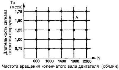
Fig. 2.364. Injector opening signal duration diagram
The power transistor of the ignition system, installed in the primary circuit of the system, is switched on and off to change the current in the primary circuit of the ignition coil. This ensures control of the change in the ignition advance angle and maintains its optimal value when changing the engine operating mode. The ignition advance angle is changed by the PCM depending on engine speed, cylinder filling with air, coolant temperature and atmospheric (barometric) pressure.
Fuel pump control
Turning on the fuel pump relay in such a way as to supply current to the pump when the engine is cranked by the starter and during its normal operation.
Control of the electromagnetic clutch of the air conditioning compressor
Turning the air conditioning compressor electromagnetic clutch on and off.
Fan relay control
The speed of the cooling system fan and the air conditioner condenser fan changes in accordance with the change in coolant temperature and vehicle speed.
Diagnostic mode
If a fault occurs in any sensor or actuator associated with the emission control system, the engine malfunction indicator lamp comes on ("CHECK ENGINE"), which informs the driver about a malfunction that has occurred.
When a malfunction occurs in any sensor or actuator, a diagnostic code corresponding to this malfunction appears.
The data from the random access memory (RAM) of the electronic engine control unit, from the sensors and actuators, can be read by the diagnostic tool. Finally, the actuators can be activated and tested independently of the system itself.
Instructions for checking for blown fuses
Remove the fuse and measure the resistance between the loaded side of the fuse and ground. Set the switches of all circuits that connect to this fuse to the on position. If the resistance is almost 0 ohms, this means there is a short circuit in the circuit between these switches and the load. If this resistance is different from 0 ohms, this means there is no short circuit in the circuit at the moment, but a momentary short circuit in the circuit causes this fuse to blow.
The main causes of short circuits are as follows:
- destruction of wiring on the car body;
- damage to the wiring insulation due to wear or heat;
- water penetration into a connector or circuit;
- human factor (incorrect connection of the circuit).
Checking the distributed fuel injection system
If the components (sensors, engine control unit, injectors, etc.) of the multi-port fuel injection (MFI) system are faulty, the result will be a stop in fuel supply or a failure in the precise fuel supply under various engine operating conditions. The following situations may occur:
- the engine does not start or starts with difficulty;
- unstable engine operation at idle;
- poor engine control.
If the above symptoms appear, it is first necessary to carry out diagnostics on the vehicle.
Diagnostic operations on the car
Memory of diagnostic trouble codes: After the PCM detects a malfunction for the first time, a diagnostic trouble code is stored and the malfunction is detected again when the engine is restarted. (The malfunction is detected during the vehicle driving cycle). However, for the fuel system (rich/lean mixture, misfire), the diagnostic trouble code will only appear the first time the malfunction is detected.
Clearing Diagnostic Trouble Codes: Once a diagnostic trouble code has been stored, and if the PCM does not detect the same malfunction again within the next 40 driving cycles, the diagnostic trouble code is cleared from the PCM memory. However, for the fuel system (rich/lean, misfire) condition, the diagnostic trouble code is cleared when the following two conditions are met:
- When the driving conditions (engine speed, coolant temperature, etc.) are identical to those under which the fault was first detected.
- When the PCM does not detect the fault again within the next 80 driving cycles.
Note: A "drive cycle" is the state of the engine when it is in the "closed-loop" mode of operation.
Malfunction Indicator Lamp (MIL)
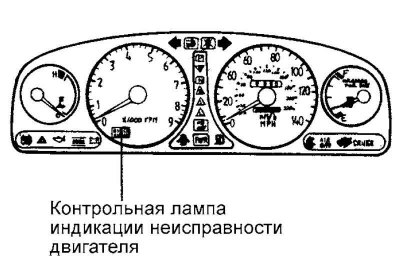
Fig. 2.365. Malfunction indicator lamp
When the Malfunction Indicator Lamp (MIL) comes on, it means there is a problem with your vehicle.
However, if no repair action is taken, the MIL will automatically turn off after 3 consecutive driving cycles.
After the ignition is turned on, the MIL comes on and stays on for about 5 seconds to indicate that the lamp is working properly.
When the MIL comes on, it may indicate that there are faults in the following components:
- catalytic converter;
- fuel system;
- mass Air Flow (MAF) Sensor;
- intake Manifold Air Temperature (IAT) Sensor;
- coolant temperature sensor (ECT);
- throttle position sensor (TPS);
- front Oxygen Sensor;
- rear oxygen sensor heater;
- rear oxygen sensor;
- front Oxygen Sensor Heater;
- injectors;
- misfires;
- crankshaft position sensor (CPS);
- camshaft position sensor (CMP);
- fuel vapor recovery system;
- vehicle speed sensor (VSS);
- idle speed control (ISC);
- electronic Engine Control Unit (ECM);
- manifold Absolute Pressure (MAP) Sensor (except for 2.7L V6 vehicles);
- fully closed throttle switch;
- exhaust gas recirculation system (except for vehicles with 2.7L V6 engine).
Verification
Turn on the ignition (ignition key position "ON") and make sure that the engine malfunction indicator lamp lights up for approximately 5 seconds and then goes out.
If the indicator lamp does not light, check the wiring for breaks, the fuse, and the lamp itself for burnout.
Self-diagnosis
The engine control unit monitors input/output signals (some constantly, others only under certain conditions). If the engine control unit detects a malfunction (a permanent or temporary malfunction of the system), it will record the corresponding malfunction code in memory and send a signal to the standard diagnostic connector. The diagnostic results (malfunction codes) can be read using the engine malfunction indicator lamp or the HI-SCAN (Pro) tester. Malfunction codes will be stored in the engine control unit memory only if there is power from the battery. Malfunction codes can be erased either by disconnecting the battery terminal or the engine control unit connector, or using the HI-SCAN (Pro) tester.
Test procedure (self-diagnosis)
Note: If the battery is discharged, it is impossible to read diagnostic codes. Monitor the battery condition (voltage of the vehicle electrical system), recharge the battery before testing.
Note: DTCs are cleared when the battery or PCM connector is disconnected. Do not disconnect the battery until all DTCs have been read and analyzed.
Testing procedure (using a GST type diagnostic device)
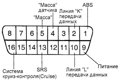
Fig. 2.366. Diagnostic connector pins
Turn off the ignition.
Connect the diagnostic tool to the data link connector (diagnostic connector).
Turn on the ignition.
Use a diagnostic tool to read the fault codes.
Perform the necessary repairs in accordance with the recommendations of the diagnostic card.
Clear diagnostic codes.
Disconnect the diagnostic tool.