
Contents: Removal ⇓ Examination ⇓ Installation ⇓ Removal, checking and installation…⇓ Removal ⇓ Examination ⇓ Installation ⇓
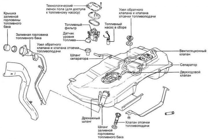
Fig. 2.394. Components of fuel lines and fuel vapor discharge lines
Removal
Remove the fuel filler cap to relieve pressure in the tank. Raise the vehicle and disconnect the fuel pump connector.
Caution: Release any residual pressure in the fuel system before disconnecting fuel lines or hoses to prevent fuel from splashing out.
When disconnecting fuel lines or hoses, cover the area with a clean rag.
Remove the fuel pump mounting screws, then remove the fuel pump assembly from the fuel tank.
Disconnect the hose and fuel return line.
Disconnect the fuel vapor bleed hose and line.
Examination
Check fuel lines and hoses for cracks, deformations, and damage.
Check the purge solenoid valve of the adsorber for blockages.
Check the fuel pump assembly for blockages and damage.
Installation
Connect the fuel vapor recovery system hose and the fuel return hose.
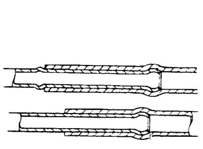
Fig. 2.395. Fuel hose connection diagram
If the fuel line has a stepped structure, connect the fuel hose as shown in Figure 2.395.
If the fuel line does not have a stepped structure, you just need to securely push the hose onto the fuel line.
Install the fuel pump assembly and secure it with the mounting bolts.
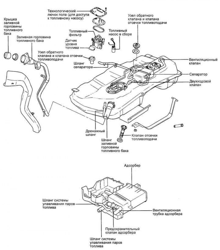
Fig. 2.396. Fuel tank components
Removal, checking and installation the fuel tank
Removal
To release residual pressure from the fuel lines and high-pressure hoses, disconnect the fuel pump connector, then start the engine and let it run. After the engine stalls on its own, turn the ignition switch to the "OFF" position.
Note: To prevent fuel splashing, make sure that the residual pressure in the high-pressure fuel lines is relieved before disconnecting the main fuel pipes and hoses.
Disconnect the cable from the negative (–) battery terminal.
Remove the fuel tank filler cap.
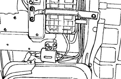
Fig. 2.397. Fuel return hoses and fuel vapor recovery systems
Disconnect the fuel return hose and the fuel vapor recovery system hose (Fig. 2.397).
Disconnect the fuel pump connector.
Disconnect the high pressure fuel hose from the fuel tank.
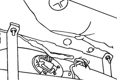
Fig. 2.398. Fuel tank mounting straps
Unscrew the two self-locking nuts and remove the two tank mounting straps (Fig. 2.398).
Disconnect the filler hose and drain hose from the fuel tank.
Remove the fuel vapor recovery system hose and fuel tank.
Examination
Check fuel lines and hoses for cracks or damage.
Check the serviceability of the cap valve and the condition of the fuel tank filler cap.
Check the fuel tank for deformation, corrosion or cracks.
Check the fuel tank for dust or foreign particles inside.
Check the in-tank fuel pump filter for damage or clogging.
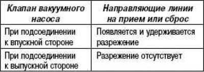
Check the two-way valve for proper operation.
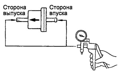
Fig. 2.399. Checking the two-way valve
Using a hand vacuum pump, check the operation of the two-way valve (Fig. 2.399).
Installation
Connect the drain hose and filler neck hose to the fuel tank so that the hose is placed on the tube at a distance of approximately 40 mm from its edge.
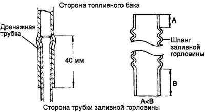
Fig. 2.400. Filler neck hose connection diagram
When connecting the filler neck hose, make sure that the end of the hose with the short straight section is positioned on the fuel tank pipe side (Fig. 2.400).
Make sure that both straps are correctly wrapped around the fuel tank. Place the fuel tank in place, tighten the self-locking nuts until they stop, i.e. until the ends of the straps touch the car body.
Connect the evaporative emission hose and the return hose. When connecting the hose to the tube, make sure the hose is pushed onto the tube as shown in the figure.
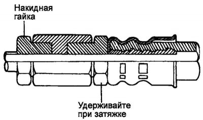
Fig. 2.401. High pressure hose connection diagram to the fuel pump
Connect the high-pressure fuel hose to the fuel pump, first tighten the union nut by hand, then tighten the nut to the rated torque. Make sure that the fuel hose is not twisted (Fig. 2.401).
Tightening torque of the high-pressure fuel hose union nut: 30–40 N·m.
Note: When tightening the union nut, do not twist or bend the fuel line to avoid damaging the fuel pump nipple.
Connect the fuel pump connector.