
Contents: Checking the fuel vapor recovery…⇓ Checking the adsorber ⇓ Checking the purge solenoid valve of…⇓
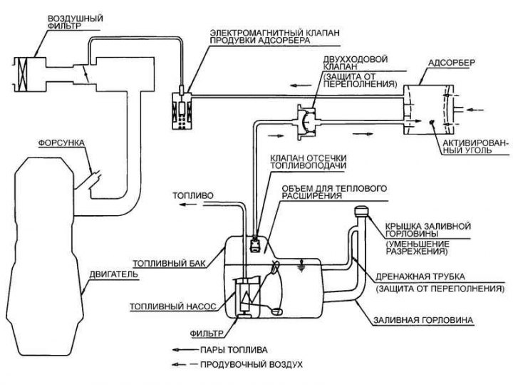
Fig. 2.222. Schematic diagram of the fuel vapor recovery system
Checking the fuel vapor recovery system
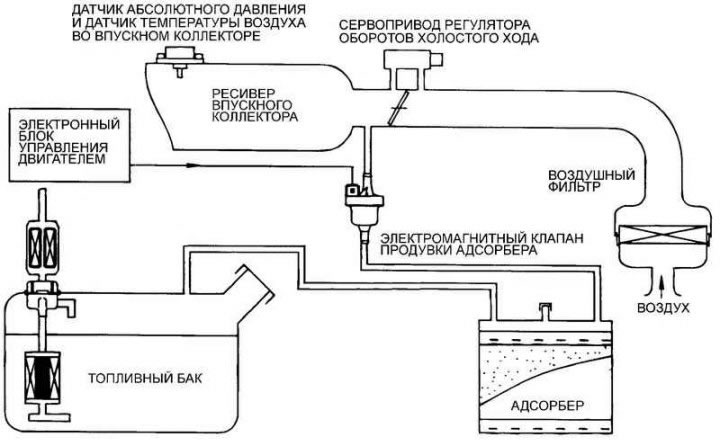
Fig. 2.223. Fuel vapor recovery system test diagram
Disconnect the vacuum hose from the throttle body and connect a hand vacuum pump to the vacuum hose.
Check the vacuum at the specified engine operating conditions, when the engine is cold (coolant temperature 60°C or below) and when the engine is warm (coolant temperature 80°C or above).
Checking the adsorber
Check the fuel vapor recovery system lines for loose connections, sharp kinks, or damage.
Check for deformation, cracks and fuel leaks.
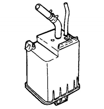
Fig. 2.224. Adsorber
After removing the adsorber, check it for cracks and deformation (Fig. 2.224).
[The article is borrowed from an online resource: HYUNDAIBOOK.RU]
Checking the purge solenoid valve of the adsorber
Note: When disconnecting vacuum hoses, always make alignment marks first so that the hoses are in their original positions when reconnected.
Disconnect the vacuum hose from the canister purge solenoid valve.
Disconnect the wiring harness connector from the solenoid valve.
Connect a hand vacuum pump to the solenoid valve fitting from which the hose with the red stripe was disconnected.
| Battery voltage | In good condition |
| Served | The vacuum decreases |
| Not served | The vacuum remains |
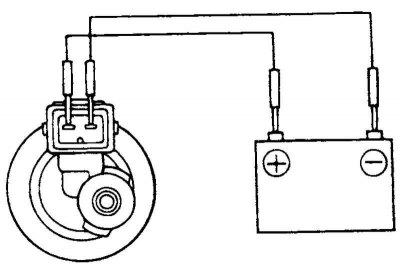
Fig. 2.225. Test diagram when connecting/disconnecting power from the battery to the terminals of the electromagnetic valve
Create a vacuum and check the operation of the valve by connecting/disconnecting the power supply from the battery to the terminals of the electromagnetic valve (Fig. 2.225).
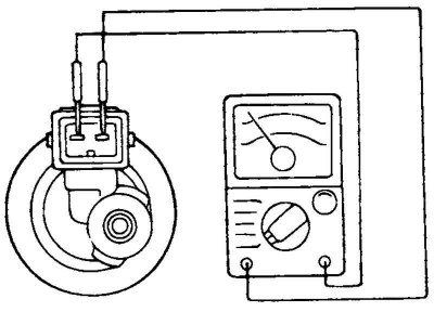
Fig. 2.226. Measuring the resistance between the terminals of the electromagnetic valve
Measure the resistance between the terminals of the solenoid valve (Fig. 2.226).
Evaporative canister purge solenoid valve: winding resistance – 26 Ohm (at a temperature of 20°C).