
Contents: Fuel tank filler cap ⇓ Removal and installation the fuel…⇓ Removal ⇓ Checking the technical condition ⇓ Installation ⇓ Removal and installation the fuel…⇓ Checking the technical condition ⇓ Installation ⇓
Fuel tank filler cap
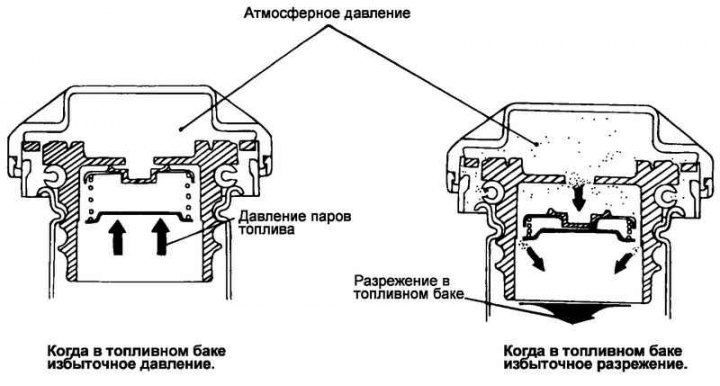
Fig. 2.227. Fuel tank filler cap
The fuel tank filler cap is equipped with a safety valve to prevent the release of fuel vapors into the atmosphere (Fig. 2.227).
Removal and installation the fuel supply control drive
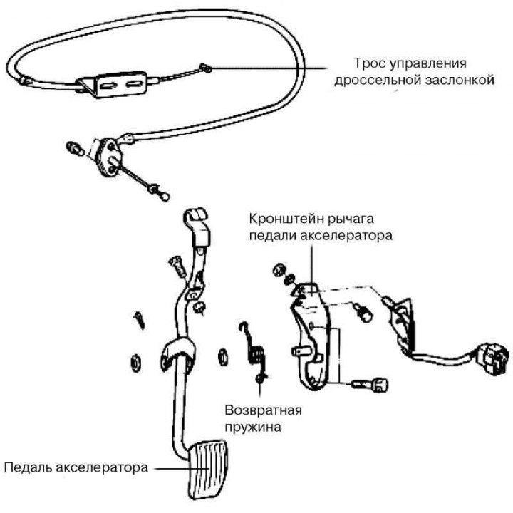
Fig. 2.228. Fuel supply control drive parts
The fuel supply control drive parts are shown in Fig. 2.228.
Removal
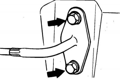
Fig. 2.229. Throttle cable bushing mounting bolts
Remove the bushing (Fig. 2.229) and the inner part of the cable from the accelerator pedal lever side.
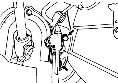
Fig. 2.230. Accelerator pedal lever bracket mounting bolts
Disconnect the electrical connector of the accelerator pedal switch, unscrew the bolts securing the accelerator pedal lever bracket (Fig. 2.230) and remove the accelerator pedal.
Checking the technical condition
Check the inside and outside of the cable for damage.
Check the smooth movement of the cable.
Check the accelerator pedal lever for deformation.
Check the return spring for damage.
Check the connection of the sleeve to the metal holder.
Check the functionality of the accelerator pedal switch.
Installation
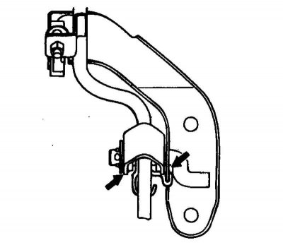
Fig. 2.231. Points of application of consistent lubricant
When installing the return spring and accelerator pedal lever, apply general-purpose grease to all friction points of the lever (Fig. 2.231).
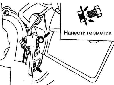
Fig. 2.232. Places of sealant application (shown by arrows)
Apply sealant to the holes for the pedal arm bracket mounting bolts (Fig. 2.232) and tighten the bolts to the specified torque.
Tightening torque of the accelerator pedal lever bracket mounting bolts: 8–12 N·m.
Securely install the plastic throttle cable bushing onto the end of the pedal arm.
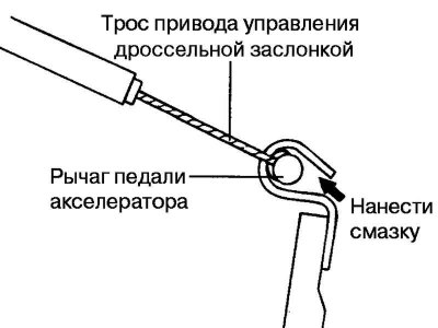
Fig. 2.233. Places of sealant application (shown by arrows)
Apply general purpose grease to the cable end (Fig. 2.233).
Removal and installation the fuel tank
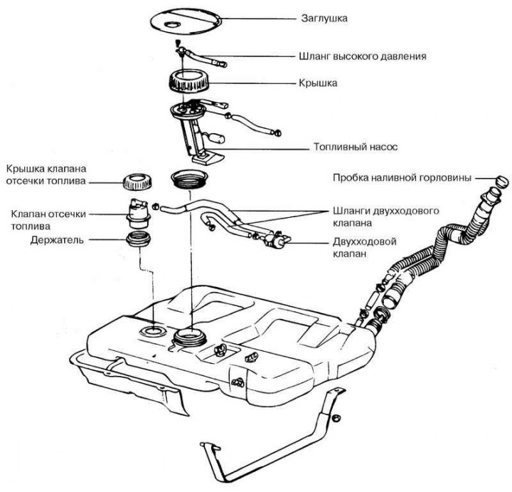
Fig. 2.234. Fuel tank
The fuel supply system consists of a fuel tank (Fig. 2.234), a fuel pump, a fuel filter, fuel lines and a fuel rail with injectors.
Fold the rear seat back onto the cushion, then fold the folded seat forward
Use a screwdriver to open the fuel pump hatch in the bottom of the body.
To relieve pressure in the fuel lines and hoses, disconnect the electrical connector from the fuel pump, start the engine and wait until the engine stops.
Note: To prevent fuel from escaping, relieve system pressure before disconnecting the fuel line and hose.
Disconnect the wire from the negative terminal of the battery.
Disconnect the high pressure hose from the fuel filter outlet fitting, disconnect the static electricity discharge wire.
Caution: To prevent fuel from escaping due to residual pressure, cover the hose connection with a rag.
Place the car on a lift.
Disconnect the fill hose and overflow tube from the tank.
Place a jack under the tank.
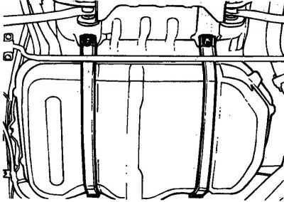
Fig. 2.235. Clamps for fastening the fuel tank to the bottom of the vehicle body
Remove the clamps securing the fuel tank to the bottom of the vehicle body (Fig. 2.235).
Carefully remove the fuel tank.
Checking the technical condition
Check hoses and lines for cracks or damage.
Check the condition of the fuel tank filler cap.
Check the fuel tank for deformation, corrosion or cracks.
Check that there is no dirt or foreign objects in the tank.
Check the internal tank filter for damage or contamination.
Check the operation of the two-way valve.
To check the two-position valve, blow lightly into it from the inlet and outlet pipes. If air passes after a slight resistance, the valve is in good condition.
Installation
Make sure the gasket is securely bonded to the tank, then install the tank and tighten the self-locking nuts securing the clamps.
Connect the overflow hose to the tank and filler neck, inserting it to a depth of approximately 40 mm.
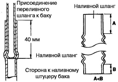
Fig. 2.236. Connection diagram of the inlet hose
Connect the inlet hose to the tank with its shorter, non-corrugated part (Fig. 2.236).
Connect the steam outlet hose.
Connect the high pressure hose to the fuel pump, being careful not to kink the hose.
Connect the fuel pump electrical connector.