


Brake system of the car Hyundai Sonata 4

Checking and adjusting the brake pedal
1. Check the gap "A" between the brake light switch and the pedal travel limiter. Rotate the brake light switch until the gap between the switch housing and the brake...
1. Check the gap "A" between the brake light switch and the pedal travel limiter. Rotate the brake light switch until the gap between the switch housing and the brake...

Checking the operation of the brake booster
1. Run the engine for one or two minutes and then turn it off. Press the brake pedal several times with the usual force when braking. If the first time you press the...
1. Run the engine for one or two minutes and then turn it off. Press the brake pedal several times with the usual force when braking. If the first time you press the...

Bleeding the brake system (models without ABS)
Note: After any work involving air entering the brake system, bleed it. The bleeding procedure is the same for each wheel brake. Bleed in the order shown in the figure....
Note: After any work involving air entering the brake system, bleed it. The bleeding procedure is the same for each wheel brake. Bleed in the order shown in the figure....

Bleeding the brake system (models with ABS)
Note: After any work involving air entering the brake system, bleed it. Perform bleeding to correctly remove air from the brake hydraulic system, fill the ABS hydraulic...
Note: After any work involving air entering the brake system, bleed it. Perform bleeding to correctly remove air from the brake hydraulic system, fill the ABS hydraulic...

Checking and adjusting the travel of the parking brake lever
1. Loosen the parking brake cable adjusting nut by turning it counterclockwise. 2. Raise and lower the parking brake lever several times with a force of 196 N. 3....
1. Loosen the parking brake cable adjusting nut by turning it counterclockwise. 2. Raise and lower the parking brake lever several times with a force of 196 N. 3....
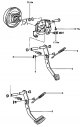
Brake pedal — removal and installation
Removing and installing the brake pedal. 1 - brake light switch, 2 - return spring, 3 - brake pedal, 4 - washer, 5 - cotter pin. Removal 1. Remove the lower instrument...
Removing and installing the brake pedal. 1 - brake light switch, 2 - return spring, 3 - brake pedal, 4 - washer, 5 - cotter pin. Removal 1. Remove the lower instrument...

Master brake cylinder
Master brake cylinder. 1 - reservoir cover, 2 - filter, 3 - brake fluid reservoir, 4 - sealing sleeve, 5 - brake master cylinder housing, 6 - secondary piston assembly...
Master brake cylinder. 1 - reservoir cover, 2 - filter, 3 - brake fluid reservoir, 4 - sealing sleeve, 5 - brake master cylinder housing, 6 - secondary piston assembly...

Vacuum brake booster
Removal and installation of the brake booster. 1 - vacuum hose, 2 - amplifier assembly, 3 - fork axle. Removal 1. Remove the brake master cylinder (see section " Master...
Removal and installation of the brake booster. 1 - vacuum hose, 2 - amplifier assembly, 3 - fork axle. Removal 1. Remove the brake master cylinder (see section " Master...

Rear axle load-sensing brake force distribution valve
General information The brake force distribution valve, depending on the rear axle load, distributes the brake fluid pressure in the brake circuits of the front and rear...
General information The brake force distribution valve, depending on the rear axle load, distributes the brake fluid pressure in the brake circuits of the front and rear...

Brake system lines
Removal Caution: Do not allow brake fluid to come into contact with painted surfaces. If brake fluid does come into contact with a painted surface, wash it off...
Removal Caution: Do not allow brake fluid to come into contact with painted surfaces. If brake fluid does come into contact with a painted surface, wash it off...

Front brake mechanism
Front brake mechanism. 1 - guide pin, 2 - dust cover, 3 - bleed nipple, 4 - caliper, 5 - cuff, 6 - piston, 7 - dust cover, 8 - caliper bracket, 9 - plate retainer, 10 -...
Front brake mechanism. 1 - guide pin, 2 - dust cover, 3 - bleed nipple, 4 - caliper, 5 - cuff, 6 - piston, 7 - dust cover, 8 - caliper bracket, 9 - plate retainer, 10 -...

Rear drum brake mechanism
Rear drum brake mechanism. 1 - fist, 2 - brake shoe, 3 - regulator, 4 - shoe adjustment lever, 5, 6 - spring, 7 - retainer spring, 8 - washer, 9 - rear wheel hub, 10 -...
Rear drum brake mechanism. 1 - fist, 2 - brake shoe, 3 - regulator, 4 - shoe adjustment lever, 5, 6 - spring, 7 - retainer spring, 8 - washer, 9 - rear wheel hub, 10 -...

Rear disc brake mechanism
Rear disc brake mechanism. 1 - brake hose, 2 - bleed nipple, 3 - caliper, 4 - fist, 5 - brake shield, 6 - brake disc. Replacing brake pads 1. Jack up the car, unscrew...
Rear disc brake mechanism. 1 - brake hose, 2 - bleed nipple, 3 - caliper, 4 - fist, 5 - brake shield, 6 - brake disc. Replacing brake pads 1. Jack up the car, unscrew...

Parking brake
Parking brake. 1 - lever button, 2 - parking brake lever, 3 - parking brake drive cables. Removal 1. Remove the floor console. 2. Loosen the parking brake lever...
Parking brake. 1 - lever button, 2 - parking brake lever, 3 - parking brake drive cables. Removal 1. Remove the floor console. 2. Loosen the parking brake lever...

ABS/EBD/TCS control unit
Removing the ABS/EBD/TCS control unit. 1 - ABS/EBD/TCS control unit (hydraulic unit and electronic control unit assembly), 2 - spacer, 3 - hydraulic unit bracket, 4 -...
Removing the ABS/EBD/TCS control unit. 1 - ABS/EBD/TCS control unit (hydraulic unit and electronic control unit assembly), 2 - spacer, 3 - hydraulic unit bracket, 4 -...

Front wheel speed sensors
Front wheel speed sensor. 1 - sensor rotor, 2 - sensor wire, 3 - wheel speed sensor. Removal 1. Loosen the front wheel speed sensor mounting bolt. Tightening torque:...
Front wheel speed sensor. 1 - sensor rotor, 2 - sensor wire, 3 - wheel speed sensor. Removal 1. Loosen the front wheel speed sensor mounting bolt. Tightening torque:...

Hydraulic diagram of ABS/EBD/TCS systems
Hydraulic diagram of ABS/EBD/TCS systems. 1 - secondary piston line of the master brake cylinder, 2 - primary piston line of the master brake cylinder, 3 - high-pressure...
Hydraulic diagram of ABS/EBD/TCS systems. 1 - secondary piston line of the master brake cylinder, 2 - primary piston line of the master brake cylinder, 3 - high-pressure...

Rear wheel speed sensors
Rear wheel speed sensor. 1 - sensor wire, 2 - wheel speed sensor. Removal 1. Remove the rear seats (see chapter " Body "). 2. Remove the rear pillar trim assembly (see...
Rear wheel speed sensor. 1 - sensor wire, 2 - wheel speed sensor. Removal 1. Remove the rear seats (see chapter " Body "). 2. Remove the rear pillar trim assembly (see...

Description of ABS/EBD/TCS systems
Brake force distribution characteristics. 1 - pressure in the rear brake lines, 2 - pressure in the front brake lines, 3 - ideal distribution, 4 - brake force...
Brake force distribution characteristics. 1 - pressure in the rear brake lines, 2 - pressure in the front brake lines, 3 - ideal distribution, 4 - brake force...

Diagnostics of ABS/EBD/TCS systems
Some deviations in the operation of the ABS system On models equipped with ABS, deviations may occur from time to time that do not indicate a malfunction. 1. Sound of...
Some deviations in the operation of the ABS system On models equipped with ABS, deviations may occur from time to time that do not indicate a malfunction. 1. Sound of...
This section is available on russian, bulgarian, belarusian, ukrainian, serbian, croatian, romanian, polish, slovak, hungarian
We recommend other sections on the topic of Hyundai manuals:
Chassis: Brake system Hyundai Accent 2 (1999-2005)
Chassis: Brake system Hyundai Elantra 2 (1995-2000, petrol)
Chassis: Brake system Hyundai Getz (2002-2011)
Chassis: Brake system Hyundai Santa Fe 2 (2007-2012, petrol)
Chassis: Brake system Hyundai Tucson 1 (2005-2010)
Chassis: Brake system Hyundai Matrix (2001-2010, petrol)
Link in different formats to this section
TextHTMLBB Code
- General information
- User manual
- Maintenance
- Power unit
- 2.0 and 2.4 liter engines
- 2.7 liter engines
- Engine overhaul
- Cooling system
- Intake and exhaust systems
- Lubrication system
- MFI fuel injection system
- Engine electrical equipment
- Transmission
- Clutch
- Mechanical gearbox
- Automatic gearbox
- Drive shafts
- Chassis
- Front suspension
- Rear suspension
- Steering
- Brake system
- Body
- Exterior
- Interior
- Heater and air conditioner
- Security systems
- Electrical equipment
- Troubleshooting
- Electrical circuits
- General information
- Maintenance
- Power unit
- Engine repair I4 DOHC
- Engine repair I4 SOHC
- Engine repair V6 SOHC
- Cooling system
- Intake and exhaust system
- Exhaust gas treatment
- Fuel system
- Transmission
- Clutch
- Mechanical gearbox
- Automatic transmission KM-175
- Automatic transmission F4A33
- Chassis
- Front suspension
- Rear suspension
- Steering
- Brake system
- Body
- Body elements
- Electrical equipment
- Equipment and devices