
Contents: Some deviations in the operation of…⇓ Checking the indicator "ABS" ⇓ Reading fault codes using a tester ⇓ Checking ABS/EBD/TCS system…⇓ Checking using the "CURRENT DATA"…⇓
Some deviations in the operation of the ABS system
On models equipped with ABS, deviations may occur from time to time that do not indicate a malfunction.
1. Sound of system functionality check.
After starting the engine, sometimes a dull sound may be heard from the engine compartment. This is a sign that the ABS system is undergoing control procedures to check its functionality.
2. Sounds of the ABS system operation.
- a) The sound of the pump motor running inside the ABS hydraulic unit (howling sound).
- b) Sound accompanied by vibration of the brake pedal (scraping).
- c) Sounds in the vehicle's chassis as a result of periodically pressing and releasing the brake pedal.
Note: A dull knock in the chassis usually comes from the suspension, and a squeal from the tires.
3. Operation of the ABS system (long braking distance).
On gravel and snowy roads, the braking distance of a car with ABS may sometimes exceed that of a car with standard brakes. Therefore, it is recommended that drivers do not be overconfident and, for safety reasons, reduce their speed when driving on such roads.
4. Feeling vibration on the brake pedal.
Vibration on the brake pedal occurs due to the operation of the ABS electromagnetic valves and is a sign of normal operation of the ABS system.
Checking the indicator "ABS"
1. Turn the ignition switch to the "ON" position and make sure that the "ABS" indicator comes on for two seconds and goes out.
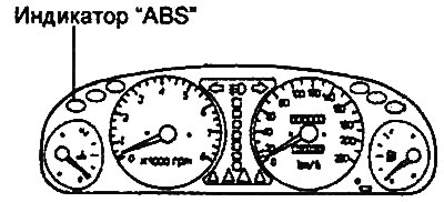
2. Make sure that the indicator does not light while the car is moving. If the indicator lights, it indicates that there are malfunctions.
Reading fault codes using a tester
1. Turn the ignition key to the "OFF" position.
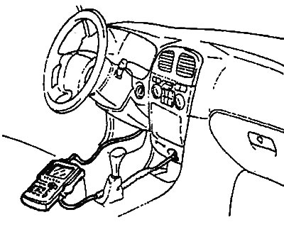
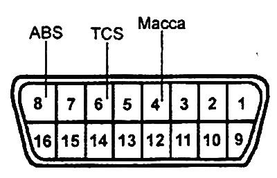
2. Connect the tester to the diagnostic connector as shown in the figure.
3. Turn the ignition key to the "ON" position.
4. Using the tester, read the diagnostic trouble codes.
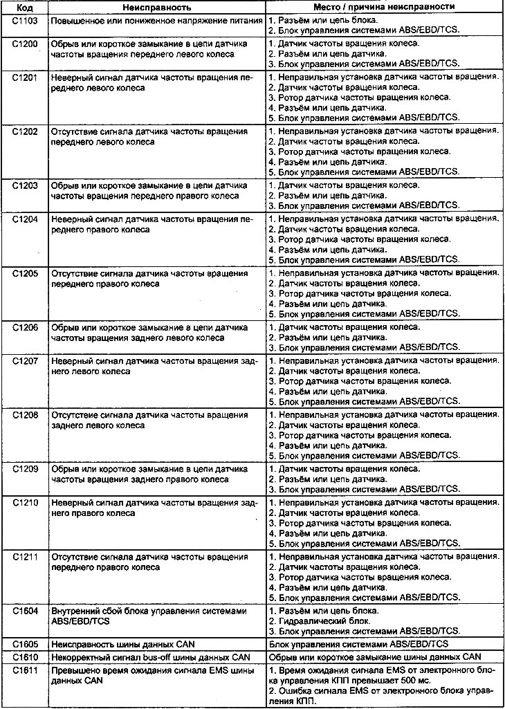
5. Determine the malfunction based on the read code and make the necessary repairs or troubleshooting (see the table "ABS/EBD/TCS system malfunction codes").
6. After completing the repair or correcting the malfunction, turn the ignition key to the "OFF" position.
7. Clear the fault codes from the electronic control unit memory using the tester reset button.
8. Disconnect the tester.
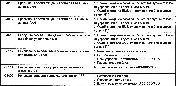
Table. ABS/EBD/TCS system fault codes.
Checking ABS/EBD/TCS system components
This operation involves checking the signals from the components at the terminals of the ABS/EBD/TCS electronic control unit connector (see the table "Signals at the terminals of the ABS/EBD/TCS electronic control unit connector").
Note: When performing the test, be careful to use sufficiently thin measuring instrument probes to avoid damaging the connector terminals.
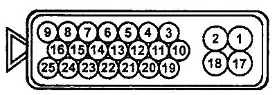
Electronic control unit connector (models before 2001).
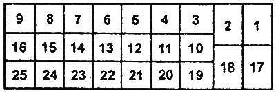
Electronic control unit connector (models since 2001).
Checking using the "CURRENT DATA" and "ACTUATOR DRIVING" functions of the tester
General verification procedures
1. With the ignition off, connect the tester to the diagnostic connector.
2. Perform a check using the "CURRENT DATA" and "ACTUATOR DRIVING" functions of the tester. If a fault is detected, check the vehicle's electrical wiring, related units and components.
3. After repair, re-test with a tester and make sure that the repair has made the abnormal input and output signal normal (conform to the standard).
4. Clear diagnostic trouble codes from the engine control unit memory.
5. Start the engine and perform a road test to ensure that the problem has been corrected.
Checking actuators with a tester
1. Turn the ignition key to the "ON" position.
2. To force the actuator to turn on, use the "ACTUATOR DRIVING" function of the tester.
Note: forced activation of the actuator is performed within 20 seconds.
Attention:
- The actuators cannot be checked if the ABS system emergency mode is activated.
- Conduct a check to ensure that the vehicle's wheels are stationary.
3. Check for the ABS valve actuation click for each channel of the hydraulic unit (FR-IN, FL-IN, RR-IN, RL-IN, FR-OUT, FL-OUT, RR-OUT, RL-OUT) when the valve is activated.
4. Check for a clicking sound from the pump motor relay when the motor is activated.
Checking system components with a tester
1. Turn the ignition key to the "ON" position.
2. To check the system components, use the "CURRENT DATA" function of the tester.
3. Check the system components (see the table Checking components using the "CURRENT DATA" function).
Table: Checking components using the "CURRENT DATA" function.
| Component symbol | Object of diagnostics |
| FL wheel speed SNSR | Front left wheel speed sensor (km/h) |
| FR wheel speed SNSR | Front right wheel speed sensor (km/h) |
| RL wheel speed SNSR | Rear left wheel speed sensor (km/h) |
| RR wheel speed SNSR | Rear right wheel speed sensor (km/h) |
| ABS SRI status | ABS indicator status |
| Brake SW | Brake light switch |
| Motor pump relay | Pump motor relay |
| Valve relay | Solenoid valve relay |
| Motor pump status | Pump motor condition |
| FL valve (In) | Front left wheel brake line inlet solenoid valve |
| FR valve (In) | Front right wheel brake line inlet solenoid valve |
| RL valve (In) | Rear left wheel brake line inlet solenoid valve |
| RR valve (In) | Rear right wheel brake line inlet solenoid valve |
| FL valve (Out) | Front left wheel brake line outlet solenoid valve |
| FR valve (Out) | Front right wheel brake line outlet solenoid valve |
| RL valve (Out) | Rear left wheel brake line outlet solenoid valve |
| RR valve (Out) | Rear right wheel brake line outlet solenoid valve |
Table. Signals at the terminals of the connector of the electronic control unit of the ABS/EBD/TCS systems (models before 2001).
| Conclusion | Signal | Designation |
| 1 | Power supply for electromagnetic valves | VLV PWR |
| 2 | Weight | GND |
| 3 | K-Line diagnostic circuit | K-Line |
| 4 | Left rear wheel speed sensor | RL |
| 5 | Left rear wheel speed sensor | RL |
| 6 | Nutrition | IG2 |
| 7 | - | - |
| 8 | Left Front Wheel Speed Sensor | FL |
| 9 | Left Front Wheel Speed Sensor | FL |
| 10 | Indicator "ABS" | ABS IND |
| 11 | - | - |
| 12 | Indicator "TCS" | TCS IND |
| 13 | TCS system switch | TCS SW |
| 14 | - | - |
| 15 | CAN data bus (signal "Low") | CAN - Low |
| 16 | CAN data bus (signal "High") | CAN - High |
| 17 | Power supply for ABS pump electric motor | ABS MTR PWR |
| 18 | Weight | GND2 |
| 19 | Right rear wheel speed sensor | RR |
| 20 | Right rear wheel speed sensor | RR |
| 21 | - | - |
| 22 | Right Front Wheel Speed Sensor | FL |
| 23 | Right Front Wheel Speed Sensor | FL |
| 24 | Brake light switch | STP |
| 25 | Indicator "TCS-OFF" | TCS-OFF IND |
Table. Signals at the terminals of the connector of the electronic control unit of the ABS/EBD/TCS systems (models since 2001).
| Conclusion | Signal | Designation |
| 1 | Left Front Wheel Speed Sensor | FL |
| 2 | Left Front Wheel Speed Sensor | FL |
| 3 | - | - |
| 4 | Nutrition | IG2 |
| 5 | Left rear wheel speed sensor | RL |
| 6 | Left rear wheel speed sensor | RL |
| 7 | K-Line diagnostic circuit | K-Line |
| 8 | Weight | GND |
| 9 | Power supply for electromagnetic valves | VLV PWR |
| 10 | CAN data bus (signal "Low") | CAN - Low |
| 11 | CAN data bus (signal "High") | CAN - High |
| 12 | - | - |
| 13 | TCS system switch | TCS SW |
| 14 | Indicator "TCS" | TCS IND |
| 15 | - | - |
| 16 | Indicator "ABS" | ABS IND |
| 17 | Indicator "TCS-OFF" | TCS-OFF IND |
| 18 | Brake light switch | STP |
| 19 | Right Front Wheel Speed Sensor | FL |
| 20 | Right Front Wheel Speed Sensor | FR |
| 21 | - | - |
| 22 | Right rear wheel speed sensor | RR |
| 23 | Right rear wheel speed sensor | RR |
| 24 | Weight | GND2 |
| 25 | Power supply for ABS pump electric motor | ABS MTR PWR |