


MFI Fuel Injection System Hyundai Sonata 4

General rules when working with an electronic control system
Attention: read the section " Rules for performing work in the engine compartment " chapters " Maintenance and general check and adjustment procedures ". Precautionary...
Attention: read the section " Rules for performing work in the engine compartment " chapters " Maintenance and general check and adjustment procedures ". Precautionary...

Fuel injection system diagnostics
General diagram of the fuel injection system (MFI) of the 2.4L engine (EOBD type). 1 - front oxygen sensor, 2 - throttle position sensor, 3 - camshaft position sensor, 4...
General diagram of the fuel injection system (MFI) of the 2.4L engine (EOBD type). 1 - front oxygen sensor, 2 - throttle position sensor, 3 - camshaft position sensor, 4...

Testing with an oscilloscope
Normal waveforms of main sensors The figures below show normal output waveforms of the main sensors. The data are given when the crankshaft speed is rapidly increasing...
Normal waveforms of main sensors The figures below show normal output waveforms of the main sensors. The data are given when the crankshaft speed is rapidly increasing...

Periodic maintenance
Checking the idle speed Note: Before starting the adjustment, check the spark plugs, injectors and idle speed control servo drive for serviceability and make sure that...
Checking the idle speed Note: Before starting the adjustment, check the spark plugs, injectors and idle speed control servo drive for serviceability and make sure that...

Adjusting the throttle position sensor (2.0L / 2.4L engines)
Note: Before testing the throttle position sensor, adjust the base idle speed. 1. Connect the tester to the standard diagnostic connector. 2. If you do not use a tester...
Note: Before testing the throttle position sensor, adjust the base idle speed. 1. Connect the tester to the standard diagnostic connector. 2. If you do not use a tester...

Adjusting the throttle position sensor (2.7L engine)
1. Turn the ignition key to the "OFF" position. 2. Disconnect the throttle position sensor connector. 3. Using the alligator clip wires, connect the ohmmeter to terminal...
1. Turn the ignition key to the "OFF" position. 2. Disconnect the throttle position sensor connector. 3. Using the alligator clip wires, connect the ohmmeter to terminal...

Checking the mass air flow sensor (2.7L engine)
General information The hot-wire air flow sensor consists of a heat-sensitive film sensor, a housing and a measuring channel (hybrid sensor element). The principle of...
General information The hot-wire air flow sensor consists of a heat-sensitive film sensor, a housing and a measuring channel (hybrid sensor element). The principle of...

Checking the Intake Air Temperature Sensor (2.7L Engine)
General information The intake air temperature sensor is located on the intake manifold. The sensor is a resistor that changes the signal voltage depending on the...
General information The intake air temperature sensor is located on the intake manifold. The sensor is a resistor that changes the signal voltage depending on the...
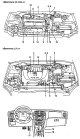
Fuel Injection System (MFI) Components
Location of fuel injection (MFI) system components. 1 - coolant temperature sensor, 2 - manifold absolute pressure sensor (2.0L engines), 3 - air flow sensor (2.7L...
Location of fuel injection (MFI) system components. 1 - coolant temperature sensor, 2 - manifold absolute pressure sensor (2.0L engines), 3 - air flow sensor (2.7L...
Checking the mass air flow sensor and intake air temperature sensor (2.4L engine)
General information The hot-wire air flow sensor consists of a heat-sensitive film sensor, a housing and a measuring channel (hybrid sensor element). The principle of...
General information The hot-wire air flow sensor consists of a heat-sensitive film sensor, a housing and a measuring channel (hybrid sensor element). The principle of...

Checking the Manifold Absolute Pressure Sensor (2.0L Engine)
General information The absolute pressure sensor in the intake manifold is a variable resistance sensitive to pressure changes. It detects the change in pressure in the...
General information The absolute pressure sensor in the intake manifold is a variable resistance sensitive to pressure changes. It detects the change in pressure in the...

Checking the coolant temperature sensor
General information The coolant temperature sensor is installed in the cooling jacket channel of the cylinder head. It detects the temperature of the engine coolant and...
General information The coolant temperature sensor is installed in the cooling jacket channel of the cylinder head. It detects the temperature of the engine coolant and...

Checking the throttle position sensor
General information The throttle position sensor is a potentiometer with a sliding contact that moves according to the rotation of the throttle axis, indicating the...
General information The throttle position sensor is a potentiometer with a sliding contact that moves according to the rotation of the throttle axis, indicating the...

Checking the camshaft position sensor
General information The operating principle of the camshaft position sensor is based on the Hall effect. The sensor determines the moment when the pistons of cylinders...
General information The operating principle of the camshaft position sensor is based on the Hall effect. The sensor determines the moment when the pistons of cylinders...

Checking the crankshaft position sensor
General information The operating principle of the crankshaft position sensor is based on the Hall effect. The sensor determines the position of the crankshaft cranks...
General information The operating principle of the crankshaft position sensor is based on the Hall effect. The sensor determines the position of the crankshaft cranks...

Checking the oxygen sensor (2.0L / 2.4L engines)
General information The oxygen sensor determines the concentration of oxygen in the exhaust gases and accordingly changes the voltage of the signal that is sent to the...
General information The oxygen sensor determines the concentration of oxygen in the exhaust gases and accordingly changes the voltage of the signal that is sent to the...

Checking the oxygen sensor with heater (2.7L engine)
General information Models with a 2.7L engine are equipped with a titanium oxygen sensor (TiO2). The oxygen sensor determines the concentration of oxygen in the exhaust...
General information Models with a 2.7L engine are equipped with a titanium oxygen sensor (TiO2). The oxygen sensor determines the concentration of oxygen in the exhaust...

Checking the injectors
General information The injectors inject fuel into the engine cylinders based on a signal from the electronic engine control unit. The amount of fuel supplied by the...
General information The injectors inject fuel into the engine cylinders based on a signal from the electronic engine control unit. The amount of fuel supplied by the...

Checking the idle speed control servo drive
General information The idle speed control servo drive is an electric motor with two windings, which are switched on by separate control circuits of the electronic...
General information The idle speed control servo drive is an electric motor with two windings, which are switched on by separate control circuits of the electronic...

Checking the knock sensor
General information The knock sensor is a piezoelectric crystal. The knock sensor is installed on the cylinder block wall to detect detonation combustion of fuel in the...
General information The knock sensor is a piezoelectric crystal. The knock sensor is installed on the cylinder block wall to detect detonation combustion of fuel in the...

Checking the pressure switch sensor for the fluid in the hydraulic system of the power steering
The power steering fluid pressure switch is sensitive to the presence of steering load and converts this data into a signal voltage. Based on this signal, the ECU...
The power steering fluid pressure switch is sensitive to the presence of steering load and converts this data into a signal voltage. Based on this signal, the ECU...

Checking the purge solenoid valve of the adsorber
General information The purge solenoid valve operates in pulse-width mode to control the air flow to purge the fuel vapor recovery system's purge canister. Engines 2.0 l...
General information The purge solenoid valve operates in pulse-width mode to control the air flow to purge the fuel vapor recovery system's purge canister. Engines 2.0 l...

Checking ignition coils
General information When the power transistor switches to the "ON" position by the signal from the engine control unit, current (12 V) will be supplied to the primary...
General information When the power transistor switches to the "ON" position by the signal from the engine control unit, current (12 V) will be supplied to the primary...

Fuel manifold — removal and installation
Fuel manifold (2.4L engine). 1 - intake manifold, 2 - throttle body, 3 - idle speed control servo, 4 - power transistor, 5 - sealing gasket, 6 - fuel manifold, 7 - fuel...
Fuel manifold (2.4L engine). 1 - intake manifold, 2 - throttle body, 3 - idle speed control servo, 4 - power transistor, 5 - sealing gasket, 6 - fuel manifold, 7 - fuel...

Fuel tank — removal, inspection, installation
Fuel tank. 1 - fuel tank filler cap, 2 - seal, 3 - fuel tank filler neck and drain hose assembly, 4 - fuel tank, 5 - fuel pump and fuel level sensor assembly, 6 - fuel...
Fuel tank. 1 - fuel tank filler cap, 2 - seal, 3 - fuel tank filler neck and drain hose assembly, 4 - fuel tank, 5 - fuel pump and fuel level sensor assembly, 6 - fuel...

Fuel lines and fuel vapor recovery system lines — removal and installation
Caution: When performing operations to remove and install parts, refer to the "Fuel tank" figure. Removal 1. Remove the fuel filler cap to relieve pressure inside the...
Caution: When performing operations to remove and install parts, refer to the "Fuel tank" figure. Removal 1. Remove the fuel filler cap to relieve pressure inside the...
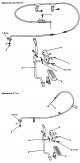
Accelerator Pedal Cable and Accelerator Pedal — Removal
Accelerator cable and pedal. 1 - adjusting bolt, 2 - connection of inner cable on the throttle body side, 3 - bushing, 4 - connection of inner cable on the accelerator...
Accelerator cable and pedal. 1 - adjusting bolt, 2 - connection of inner cable on the throttle body side, 3 - bushing, 4 - connection of inner cable on the accelerator...

Toxicity Reduction System — General Information
Location of emission control system components in the engine compartment. 1 - forced crankcase ventilation valve, 2 - electromagnetic valve for purging the adsorber, 3 -...
Location of emission control system components in the engine compartment. 1 - forced crankcase ventilation valve, 2 - electromagnetic valve for purging the adsorber, 3 -...

Forced crankcase ventilation system
Operation diagram of the forced crankcase ventilation system (2.7 l engine). System check 1. Disconnect the ventilation hose from the positive crankcase ventilation...
Operation diagram of the forced crankcase ventilation system (2.7 l engine). System check 1. Disconnect the ventilation hose from the positive crankcase ventilation...

Fuel vapor recovery system
Fuel vapor recovery system diagram Note: The procedure for checking the two-way and check valves is given in Chapter " Multi-fuel injection system (MFI) ". System check...
Fuel vapor recovery system diagram Note: The procedure for checking the two-way and check valves is given in Chapter " Multi-fuel injection system (MFI) ". System check...
Emissions reduction system — troubleshooting by their signs
Sign of malfunction Probable cause Elimination The engine does not start or starts with difficulty The vacuum hose is disconnected or damaged. Malfunction of the purge...
Sign of malfunction Probable cause Elimination The engine does not start or starts with difficulty The vacuum hose is disconnected or damaged. Malfunction of the purge...
This section is available on russian, bulgarian, belarusian, ukrainian, serbian, croatian, romanian, polish, slovak, hungarian
We recommend other sections on the topic of Hyundai manuals:
Power unit: Fuel injection system Hyundai Elantra 1 (1990-1995, petrol)
Link in different formats to this section
TextHTMLBB Code
- General information
- User manual
- Maintenance
- Power unit
- 2.0 and 2.4 liter engines
- 2.7 liter engines
- Engine overhaul
- Cooling system
- Intake and exhaust systems
- Lubrication system
- MFI fuel injection system
- Engine electrical equipment
- Transmission
- Clutch
- Mechanical gearbox
- Automatic gearbox
- Drive shafts
- Chassis
- Front suspension
- Rear suspension
- Steering
- Brake system
- Body
- Exterior
- Interior
- Heater and air conditioner
- Security systems
- Electrical equipment
- Troubleshooting
- Electrical circuits
- General information
- Maintenance
- Power unit
- Engine repair I4 DOHC
- Engine repair I4 SOHC
- Engine repair V6 SOHC
- Cooling system
- Intake and exhaust system
- Exhaust gas treatment
- Fuel system
- Transmission
- Clutch
- Mechanical gearbox
- Automatic transmission KM-175
- Automatic transmission F4A33
- Chassis
- Front suspension
- Rear suspension
- Steering
- Brake system
- Body
- Body elements
- Electrical equipment
- Equipment and devices