Contents: System check ⇓ Checking the adsorber ⇓ Checking the purge solenoid valve of…⇓ Checking the vacuum hose nipple for…⇓ Checking the fuel filler cap ⇓
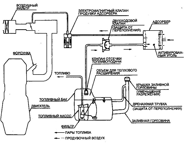
Fuel vapor recovery system diagram
Note: The procedure for checking the two-way and check valves is given in Chapter "Multi-fuel injection system (MFI)".
System check
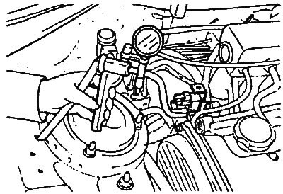
1. Disconnect the vacuum hose (with red stripe) from the throttle body and connect a hand vacuum pump to the vacuum hose.
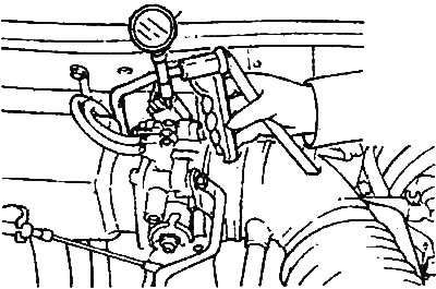
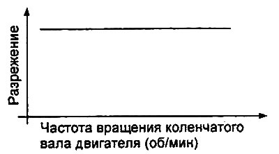
2. Check the vacuum at the specified engine operating conditions, when the engine is cold (coolant temperature 60°C or lower) and when the engine is warm (coolant temperature 80°C or higher).
- a) When the engine is cold, in good condition, in idle mode and at an engine crankshaft speed of 3000 rpm, the created vacuum remains at a level of 50 kPa.
- b) When the engine is warm, then:
- In idle mode, the created vacuum is maintained at 50 kPa.
- For approximately 3 minutes after the engine reaches 3000 rpm, an attempt is made to create a vacuum and the vacuum decreases.
- Three minutes after the engine reaches 3000 rpm, the vacuum created will be 50 kPa, will be maintained for a moment and then decrease again.
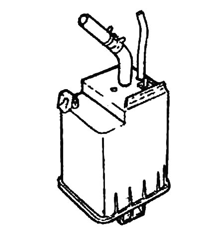
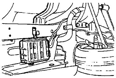
Checking the adsorber
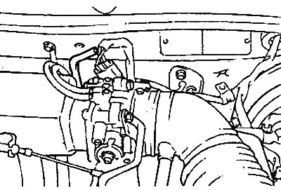
1. Check the fuel vapor recovery system lines for loose connections, sharp kinks, or damage.
2. Check for deformation, cracks and fuel leaks.
3. After removing the adsorber, check it for cracks and deformation.
 |
 |
Checking the purge solenoid valve of the adsorber
Note:
- The vehicle is equipped with an electromagnetic purge valve for the adsorber with a pulse-width control mode.
- When disconnecting vacuum hoses, always make alignment marks first so that the hoses are in their original positions when reconnected.
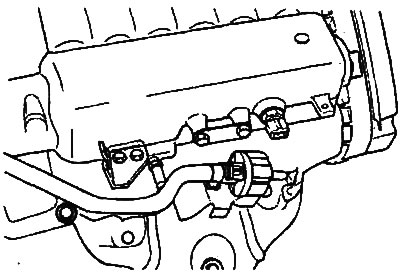
1. Disconnect the vacuum hose (black with red stripe) from the canister purge solenoid valve.
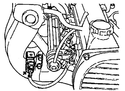
Engines 2.0 l/2.4 l. |
Engine 2.7 l. |
2. Disconnect the wiring harness connector from the solenoid valve.
3. Connect a hand vacuum pump to the solenoid valve fitting from which the vacuum hose with the red stripe was disconnected.
4. Create a vacuum and check the operation of the valve by connecting/disconnecting the power supply from the battery to the terminals of the solenoid valve.
- a) If the valve is in good condition, the vacuum will decrease when battery voltage is applied.
- b) If the valve is in good condition, the vacuum will be maintained when battery voltage is not supplied.
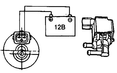
5. Measure the resistance of the winding between the terminals of the purge solenoid valve.
- Nominal value (at 20°C): 26 Ohm
Checking the vacuum hose nipple for purging the adsorber
Note: Before checking, warm up the engine until the coolant temperature reaches 80-90°C.
1. Disconnect the vacuum hose from the purge channel fitting on the intake manifold and connect a hand vacuum pump to the fitting.
2. Start the engine and check that as the engine crankshaft speed increases, the vacuum remains almost constant.
Note: If vacuum is not created, there is likely deposits in the vacuum hose fitting channel (in the throttle body) and it needs to be cleaned.
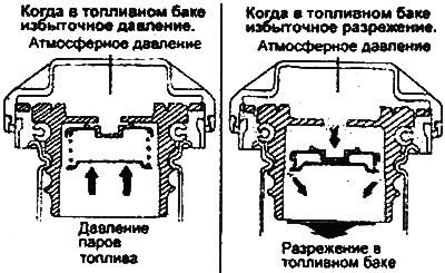
Checking the fuel filler cap
1. Check the condition of the O-ring gasket of the cap and the fuel filler cap (absence of damage or deformation). If necessary, replace the filler cap.
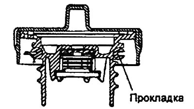
2. The fuel tank filler cap is equipped with a safety valve to prevent fuel vapors from escaping into the atmosphere. Check that the safety valve functions normally both under excess pressure in the fuel tank and under excess vacuum in the fuel tank (see figure).