
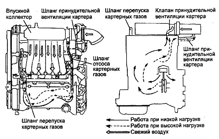
Operation diagram of the forced crankcase ventilation system (2.7 l engine).
System check
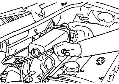
1. Disconnect the ventilation hose from the positive crankcase ventilation valve. Remove the valve from the cylinder head cover and connect it to the ventilation hose.
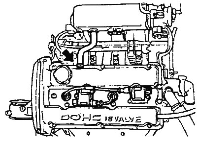
Engines 2.0 l / 2.4 l. |
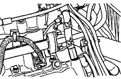
Engine 2.7 l. |
2. Start the engine and let it idle. Cover the valve hole with your finger and make sure that you feel a vacuum from the intake manifold.
Note: At this point, the PCV valve plunger will move back and forth.
3. If there is no vacuum, clean the positive crankcase ventilation valve and ventilation hose in a cleaning solution (solvent) or replace if necessary.
Checking the Positive Crankcase Ventilation Valve
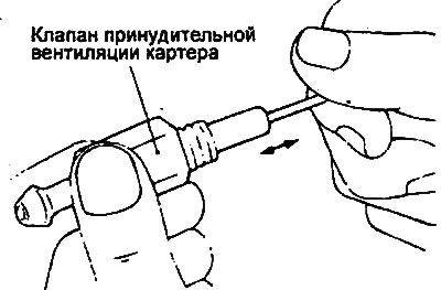
1. Remove the positive crankcase ventilation valve.
2. Insert a thin rod into the positive crankcase ventilation valve from the threaded side and, by moving the rod back and forth, check that the plunger moves.
3. If the plunger does not move, there are deposits in the positive crankcase ventilation valve. In this case, it is necessary to clean or replace the valve.
4. Install the positive crankcase ventilation valve in place and tighten it to the specified torque.
- Tightening torque: 8-12 Nm
Description of the operation of the positive crankcase ventilation valve
The crankcase ventilation valve is designed to regulate the flow of crankcase gases passed to the intake. The following four operating modes of the crankcase ventilation valve are possible.
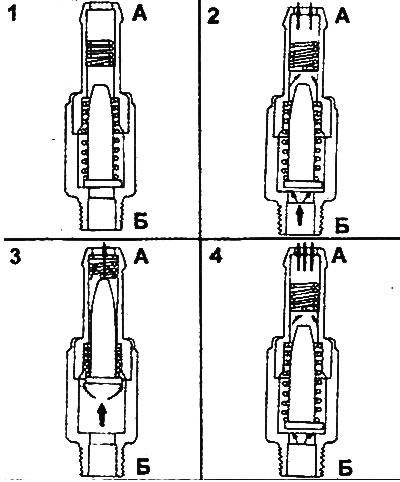
A - from the intake manifold side; B - from the cylinder head cover side; 1 - no vacuum; 2 - medium vacuum; 3 - high vacuum; 4 - low vacuum.
1. There is no vacuum.
When the engine is not running, the valve is completely closed by the main spring and gases from the crankcase do not enter the intake manifold. The valve acts similarly during a backfire (the so-called "shot into the intake") to prevent flames from entering the crankcase, where they can ignite concentrated fuel vapors.
(Material was obtained from an official resource: HYUNDAIBOOK)
2. Medium vacuum.
When the car is moving with a light load on the engine, the valve spool occupies an intermediate position (the valve is open), allowing a larger amount of crankcase gases to pass through.
3. Large vacuum.
When the engine is idling and when the car slows down (forced idle), a small amount of crankcase gases is formed, but the vacuum in the intake manifold channel is large. As a result, the valve spool is completely drawn in, overcoming the resistance of the springs, and significantly closes the vacuum channel, so that, despite the full opening of the forced ventilation channel, the bypass of crankcase gases is minimal and excess air is not sucked into the intake from the air filter.
4. Low vacuum.
When accelerating the car and driving with a high engine load, a large amount of crankcase gases is formed, so that the valve spool takes a position in which the vacuum channel has a maximum cross-section (the crankcase ventilation valve is almost closed). If the amount of crankcase gases formed exceeds the valve's throughput, some of them are sent through the ventilation hose to the air filter housing and then to the intake.