
Contents: General information ⇓ Troubleshooting Guide ⇓ Checking the resistance of the servo…⇓ Checking with a tester ⇓
General information
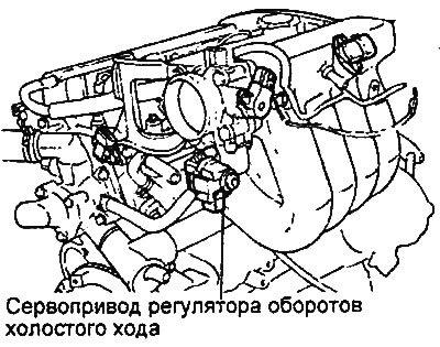
The idle speed control servo drive is an electric motor with two windings, which are switched on by separate control circuits of the electronic engine control unit. Depending on the pulse period fill factor, the difference in magnetic forces of the two windings will rotate the electric motor shaft by a certain angle, thus changing the flow section of the bypass channel. The bypass channel is located in the throttle body parallel to the throttle channel in the place where the idle speed control servo drive is installed.
- Control unit control signal frequency: 90-110 Hz
Engines 2.0 l / 2.4 l. |
Engine 2.7 l. |
Troubleshooting Guide
Under the following conditions, the engine malfunction indicator lamp comes on and the corresponding malfunction code is displayed on the tester.
1. If there is an open circuit or short circuit in the primary voltage circuit on the engine control unit side.
2. If the ignition timing control by the electronic engine control unit is disrupted.
3. If an open or short circuit is detected in the idle speed control servo circuit after the ignition is turned on.
Checking the resistance of the servo drive windings
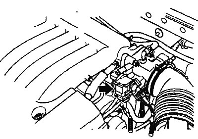
1. Disconnect the idle speed control servo connector.
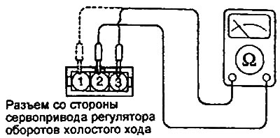
2. Measure the resistance between the connector terminals.
Nominal value (at 20°C):
- Pins "3" and "2": 10.5-14.0 Ohm
- Pins "1" and "2": 10.0-12.5 Ohm
3. Securely connect the idle speed control servo connector.
- Tightening torque of the idle speed control servo drive: 6-8 Nm
Checking with a tester
Start the engine and check that the idle speed control servo is activated (the idle speed control servo operates, the engine speed increases or decreases).