
Contents: Fan mode switch ⇓ Air intake mode selection button ⇓ Ventilation mode selection switch ⇓ "in the head area" ⇓ "in the area of the legs / in the…⇓ "in the leg area" ⇓ "in the foot area/to the windshield…⇓ "to the windshield and side window…⇓ Air temperature control knob ⇓
Fan mode switch
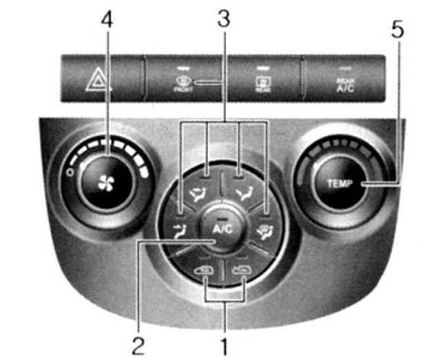
Fig. 1.111. Control panel of the heater and ventilation system: 1 – air intake mode selection switch; 2 – air conditioner switch; 3 – ventilation mode selection switch; 4 – fan speed mode selection switch; 5 – air temperature control switch
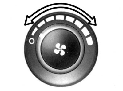
Fig. 1.112. Fan mode switch
The fan operates only if the ignition key is in the "ON" position (Fig. 1.112).
This switch is used to turn the fan on and off and select its rotation speed. The fan speed, and therefore the amount of air flow coming from the ventilation system, can be changed manually by turning this switch. When turning the switch to the right, the air flow increases, when turning to the left, it decreases.
To turn off the fan, move the switch to the "0" position.
Air intake mode selection button
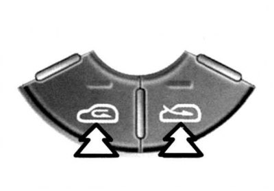
Fig. 1.113. Air intake mode selection button
This switch is used to change the ventilation modes between the outside air intake mode and the recirculation mode. To change the ventilation modes (outside air intake mode, air recirculation mode), press this button (Fig. 1.113).
Outdoor air intake mode
Air recirculation mode
In outside air intake mode ("FRESH") outside air enters the vehicle interior, heated or cooled depending on the selection of other functions.
In air recirculation mode ("RECIRCULATION") the air in the car's interior is recirculated and heated or cooled depending on the selection of other functions.
Note: Using the air recirculation modeover a long period of time can cause the windshield and side windows to fog up, and the air inside the car will become stale and excessively dry. If the air conditioner is used in recirculation mode for a long time,
the air inside the car will also become excessively dry.
Ventilation mode selection switch
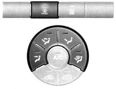
Fig. 1.114. Ventilation mode selection switch
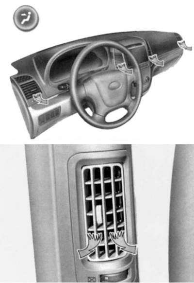
Fig. 1.115. Ventilation supply to the head area
This switch is used to select the direction of air flow to the feet, through the deflectors into the passenger compartment or to the windshield (Fig. 1.115). To indicate the ventilation modes (to the head area; in the leg area/in the head area; in the leg area; in the foot area/ to the windshield and side window heating deflectors; (for the windshield and side window heating deflectors) five symbols are used.
"in the head area"
The air flow through the deflectors enters the upper part of the car interior (Fig. 1.115).
"in the area of the legs / in the area of the head"
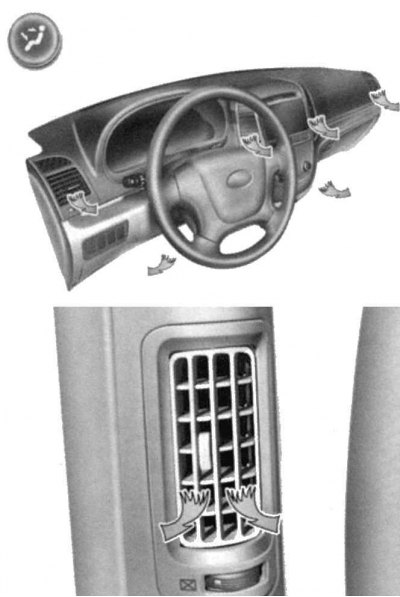
Fig. 1.116. Ventilation supply to the head and feet area
Air flows through the deflectors into the upper part of the car interior and into the footwell area (Fig. 1.116). This allows warm air to flow through the deflectors to the footwells, and unheated or slightly heated air to flow through the deflectors into the upper part of the interior.
"in the leg area"
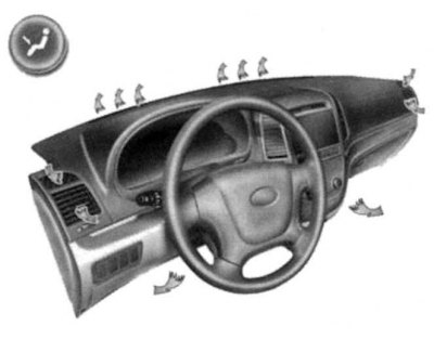
Fig. 1.117. Ventilation supply to the leg area
Air is supplied to the leg area (Fig. 1.117).
"in the foot area/to the windshield and side window heating deflectors"
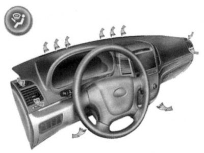
Fig. 1.118. Ventilation supply to the footwell/to the windshield and side window heating deflectors
Air is supplied through the windshield deflectors, side windows and into the footwell area (Fig. 1.118).
When selecting a mode (to the footwell/to the windshield and side window heating deflectors), the air conditioner is automatically turned on and the outside air intake mode is set ("FRESH").
"to the windshield and side window heating deflectors"
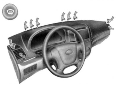
Fig. 1.119. Ventilation supply to the windshield and side window heating deflectors
Air is supplied through the windshield and side window deflectors (Fig. 1.119).
When this mode is selected, the air conditioner is automatically turned on and the outside air intake mode is set ("FRESH").
Air temperature control knob
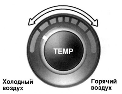
Fig. 1.120. Air temperature control knob
This handle is used to turn the heater on and off and to select the desired air temperature (Fig. 1.120).