
Normal waveforms of main sensors
The figures below show normal output waveforms of the main sensors. The data are given when the crankshaft speed is rapidly increasing (accelerating) to 4800 rpm with no engine load and the engine is sufficiently warmed up. The data in each figure is only a reference value, and actual data may differ significantly from them.
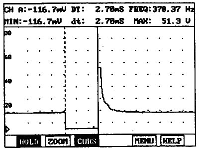
1. Signal from the camshaft position sensor (CMP) and the crankshaft position sensor (CPS).
The signal frequency should gradually increase as you press the accelerator pedal and should gradually decrease after you release the pedal without any sudden drops or jumps.
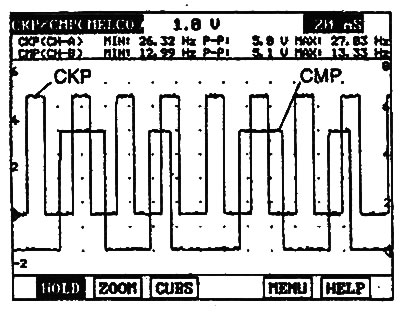
Engines 2.0 l / 2.4 l. |
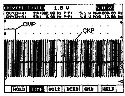
Engine 2.7 l. |
2. Signal from the mass air flow sensor (MAF, 2.7L engine only) and throttle position sensor (TPS).
- a) The air flow sensor signal should increase when the accelerator pedal is pressed and should decrease when the throttle valve is fully closed (with the accelerator pedal released).
- b) The throttle position sensor signal should increase when the accelerator pedal is pressed and should decrease when the pedal is released.
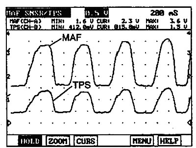
Engines 2.0 l / 2.4 l. |
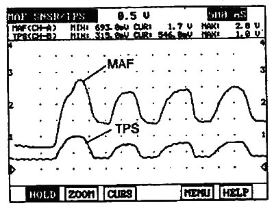
Engine 2.7 l. |
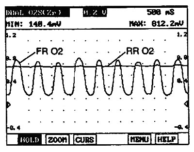
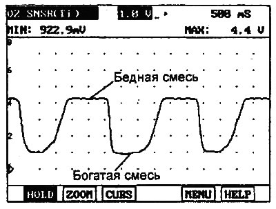
3. Signal from front (FR) and rear (RR) oxygen sensors.
The front and rear oxygen sensor signals may increase immediately after pressing the accelerator pedal and may decrease when the pedal is released.
Engines 2.0 l/2.4 l. |
2.7L engine (non-EOBD models). |
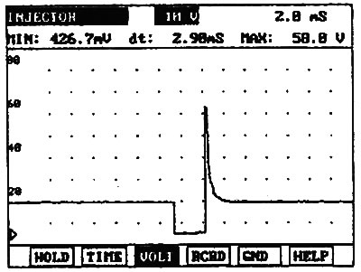
4. Injector control signal.
The signal should increase when the accelerator pedal is pressed and should decrease when the pedal is released.
Engines 2.0 l/2.4 l. |
Engine 2.7 l |