
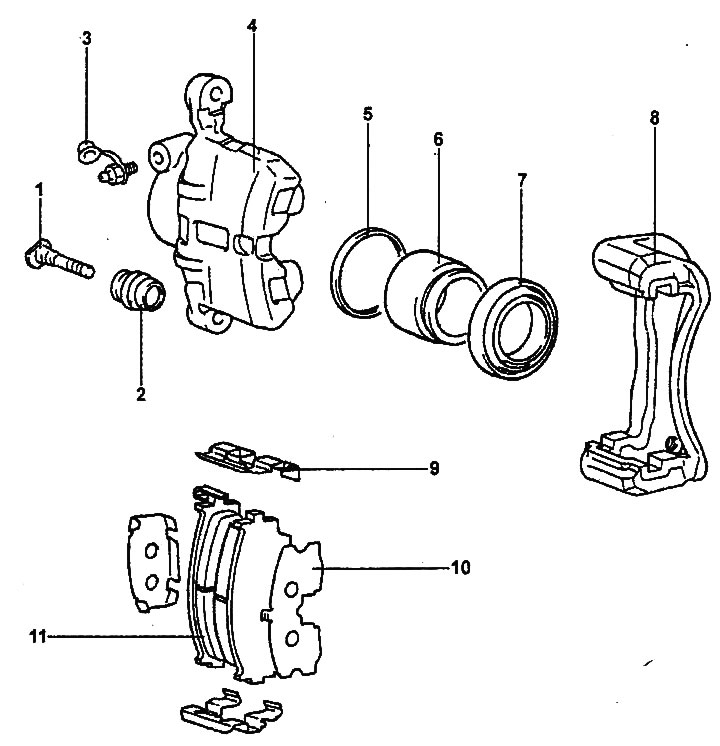
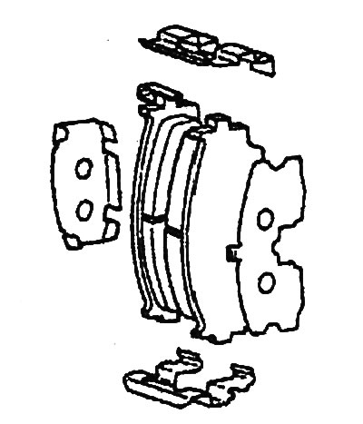
Front brake mechanism.
1 - guide pin, 2 - dust cover, 3 - bleed nipple, 4 - caliper, 5 - cuff, 6 - piston, 7 - dust cover, 8 - caliper bracket, 9 - plate retainer, 10 - anti-squeak gasket, 11 - brake shoe.
Replacing brake pads
1. Jack up the car, unscrew the bolts and remove the front wheel.
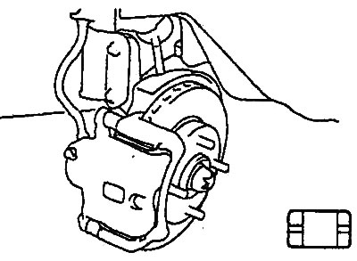
2. Check the thickness of the brake pads through the inspection hole in the caliper. Replace the pads if necessary.
- Nominal thickness: 11 mm
- Minimum thickness: 2 mm
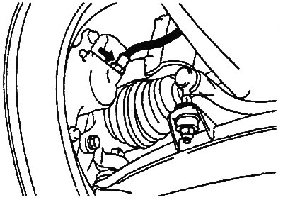
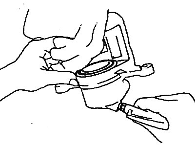
3. Raise the caliper.
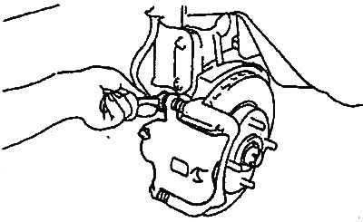
- a) Remove the guide pins.
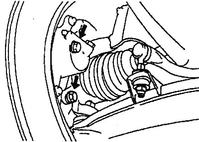
- b) Raise the caliper and secure it as shown in the figure.
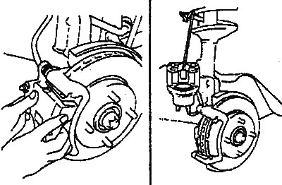
Caution: Do not disconnect the brake hose from the caliper.
4. Remove the brake pads, linings and retaining plates.
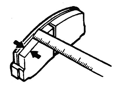
5. Measure the thickness of the brake shoe lining at the point of greatest wear.
- Nominal thickness: 11 mm
- Minimum thickness: 2 mm
If the brake pad lining thickness is less than the minimum value, replace the brake pads.
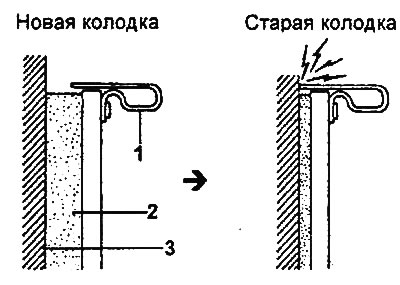
Wear of brake pad linings
1 - lining wear indicator, 2 - lining, 3 - brake disc.
[The original material is located on the website HyundaiBook]
Attention:
- When a brake pad needs to be replaced, replace the entire set of brake pads on both the left and right sides of the vehicle. Do not mix brake pads of different types or manufacturers in the same set.
- All four brake pads must be replaced as a set.
- When replacing brake pads, check for deformation. When replacing brake pad retainers, install a new or used retainer only after cleaning it from foreign particles.
- If there is a noticeable difference in the thickness of the brake shoe linings on the left and right sides, check the smooth movement of the piston, guide and locking pins.
6. Install the brake pad retainers into the caliper bracket.
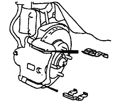
7. Install the brake pads.
Note: Install the brake pad with the lining wear indicator facing up.
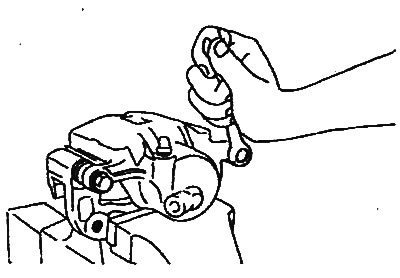
8. Press the piston into the caliper using a hammer handle or something similar.
9. Install the boot into the caliper.
Note: Be careful not to damage the boot.
10. Install two guide pins.
- Tightening torque: 22-32 Nm
11. Install the front wheel and tighten the bolts.
- Tightening torque: 90-110 Nm
Removal
1. Jack up the car, unscrew the bolts and remove the front wheel.
- Tightening torque: 90-110 Nm
2. Disconnect the brake hose from the caliper.
- Tightening torque: 7-13 Nm
3. Remove the brake mechanism assembly.
Disassembly
1. Unscrew the guide pins and detach the caliper from the bracket.
- Tightening torque: 22-32 Nm
2. Using a screwdriver, remove the boot ring.
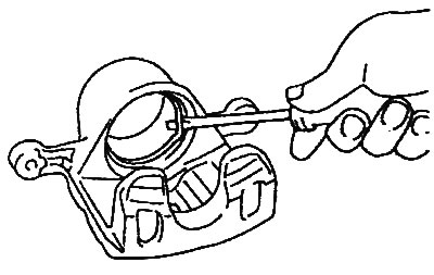
3. Remove the boot from the caliper.
4. Using compressed air, remove the piston.
Caution: Do not place your fingers in front of the piston when applying compressed air.
5. Using a screwdriver, remove the cuff.
Caution: Be careful not to damage the cylinder walls.
Examination
1. Clean the outer surface of the piston and the inner surface of the cylinder with brake fluid.
2. Check the brake cylinder for wear, damage and rust.
3. Check the inner diameter of the cylinder.
- Nominal internal diameter: 57.2 mm
4. Check the piston surface for wear, damage and rust.
5. Check the brake pads for deformation and damage.
6. Check that the wear indicator pad is not damaged.
7. Check the thickness of the brake disc.
- a) Using a micrometer, measure the thickness of the brake disc at eight points approximately every 45° at a distance of 10 mm from the outer edge of the disc.
- Nominal thickness: 24.5 mm
- Minimum thickness: 22.4 mm
- b) Calculate the difference between the maximum and minimum values of the brake disc thickness obtained in step "a". Make sure that the maximum difference does not exceed the permissible value.
- Difference in brake disc thickness values: 0.005 mm
- c) If the obtained values do not correspond to the technical data, replace the disk with a new one.
8. Check the outer diameter of the brake disc.
- Brake disc outer diameter: 257 mm
9. Check the brake disc runout
- a) Using a dial indicator, measure the runout of the brake disc at a distance of approximately 5 mm from the outer edge of the disc.
- Maximum permissible value: 0.03 mm
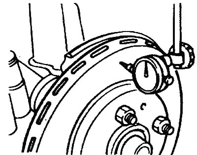
- b) If the runout value of the brake disc does not correspond to the technical data, replace the disc.
Assembly
Assembly is carried out in the reverse order of disassembly.
Installation
1. The brake mechanism is installed in the reverse order of removal; the tightening torques for the bolts and nuts are specified in the text describing the removal procedure.
2. After installation, bleed the brake system.