
Contents: Removal ⇓ Checking and replacing front disc…⇓ Checking the thickness of the brake…⇓ Checking the runout of the front…⇓ Correction of brake disc runout ⇓ Installation ⇓
Removal
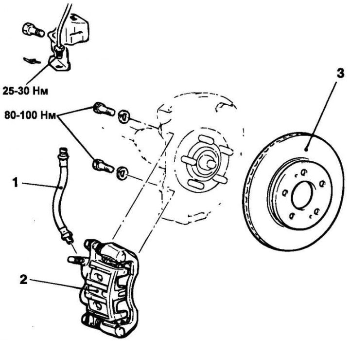
Fig. 6.22. Front disc brake: 1 – connecting tube (brake hose and tube assembly); 2 – front brake caliper assembly; 3 – brake disc
The components of the front disc brake are shown in Fig. 6.22.
Checking and replacing front disc brake pads
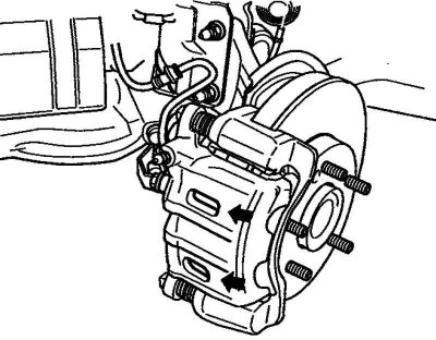
Fig. 6.23. Technological holes of the support
Check the thickness of the brake pad linings through the technological holes in the caliper (Fig. 6.23).
Attention! If the thickness of the brake shoe lining is less than the maximum permissible value, replace the brake shoes on the left and right wheels as a set.
If there is a noticeable difference in the thickness of the brake pad linings on the left and right sides of the caliper, check the smoothness of the caliper movement along the guide and stop pin bushings.
Remove the guide pin, lift the caliper assembly up and suspend it with wire.
Note: Be careful not to get grease on the locking and guide pins.
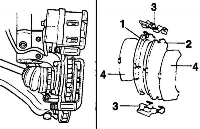
Fig. 6.24. The order of extracting parts from the support: 1 – brake shoe and indicator assembly; 2 – brake shoe assembly; 3 – retainer; 4 – outer gasket
Remove the parts from the support in the order shown in Figure 6.24.
Checking the thickness of the brake disc
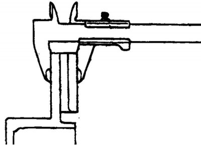
Fig. 6.25. Measuring the thickness of the brake disc
Using a micrometer, measure the thickness of the brake disc at eight points approximately every 45° at a distance of 10 mm from the outer edge of the disc (Fig. 6.25).
Brake disc thickness:
- nominal value – 26 mm;
- maximum permissible value: 24.4 mm.
Note: Thickness changes are made at least in 8 points.
If the disc thickness does not correspond to the maximum permissible value or the disc is unevenly worn, remove it and install a new one.
Checking the runout of the front brake disc
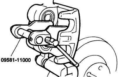
Fig. 6.26. Removing the brake caliper
Remove the caliper assembly, lift it and secure it to the side with wire (Fig. 6.26).
Note: Tighten the wheel nuts to secure the brake disc to the hub.
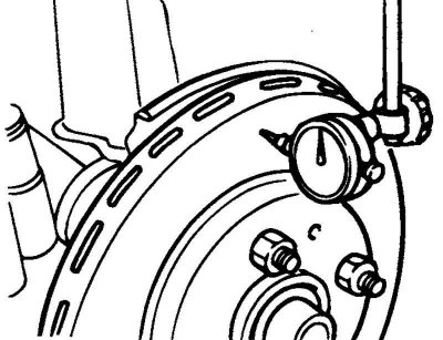
Fig. 6.27. Measuring the runout of the brake disc
Place a dial indicator approximately 5 mm from the outer edge of the brake disc and measure the disc runout (Fig. 6.27).
Maximum permissible value: 0.04 mm.
Correction of brake disc runout
If the runout value of the brake disc corresponds to or exceeds the maximum permissible value, try changing the relative position of the disc and the wheel hub, and then measure the runout again.
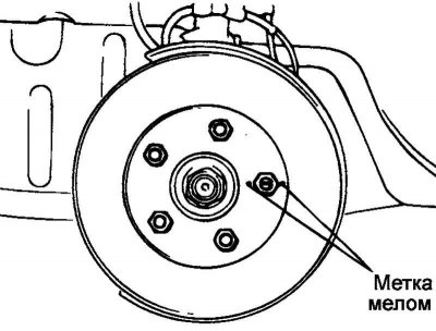
Fig. 6.28. Places of application of marks
Before removing the brake disc, at the point of maximum runout, make marks with chalk on both sides of the wheel stud (Fig. 6.28).
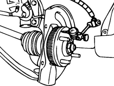
Fig. 6.29. Measuring axial clearance in the hub bearing
Remove the brake disc and install a dial indicator as shown in Figure 6.29. By moving the hub axially, measure the axial clearance in the hub bearing.
Maximum permissible value: 0.05 mm.
If the axial clearance is equal to or exceeds the maximum permissible value, remove the hub and inspect the steering knuckle and hub.
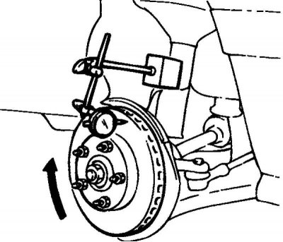
Fig. 6.30. Re-measuring the brake disc runout
If the axial clearance in the hub bearing does not exceed the maximum permissible value, then turn the brake disc 180° from the chalk line, install it on the hub, and repeat the brake disc runout measurement again (Fig. 6.30).
If the operations performed do not eliminate the increased runout of the disc, then it is necessary to replace the brake disc.
Installation
Install the brake shoe retainers.
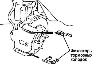
Fig. 6.31. Brake shoe retainers
Install the brake pads into the brake pad retainers (Fig. 6.31).
Note: All four brake pads must be replaced as a set.
Note: When replacing brake pads, check for deformation. When replacing brake pad retainers, install a new or used retainer only after cleaning it from foreign particles.
Insert the piston into the working brake cylinder using a special tool or using the handle of a plastic hammer.
Carefully install the caliper assembly so as not to damage the piston dust boot.
Tighten the two guide pins to the specified torque: 22–32 N·m.