
Contents: Electronic Brakeforce Distribution…⇓ Advantages of electronic control ⇓ Comparison of brake force…⇓ Checking the hydraulic and…⇓ ABS Electronic Control Unit (HECU)…⇓
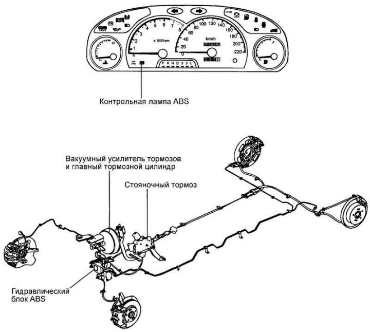
Fig. 6.56. Location of system components
The anti-lock braking system (ABS) controls the pressure in the brake circuits of all four wheels when braking on dangerous (slippery) road sections, preventing the wheels from locking. The ABS system provides the following benefits:
- allows you to avoid an obstacle with a high degree of confidence, even in the event of emergency braking;
- allows you to stop the car during emergency braking while maintaining control and stability on the road, even on a curved trajectory.
In case of malfunction, the diagnostic function and emergency operation function included in the system ensure ease of operation and maintenance.
The ABS Integrated Control Unit (HESU), consisting of the ABS hydraulic unit and ABS electronic control unit assembly, receives signals about vehicle speed, road surface conditions and direction of travel from the wheel speed sensors.
Based on these signals, the electronic control unit determines the optimal wheel rotation speed.
Electronic Brakeforce Distribution (EBD)
The use of electronic brake force distribution, compared to the installation of a proportional valve, ensures ideal pressure distribution in the front and rear brake circuits. As a result, braking efficiency is significantly increased and locking of the rear wheels is prevented.
Advantages of electronic control
Functional improvement of the parameters of the main braking system.
Compensation for different coefficients of wheel-road adhesion.
Elimination of the installation of a proportional valve.
Indication of faults by means of a control lamp.
Comparison of brake force distribution characteristics
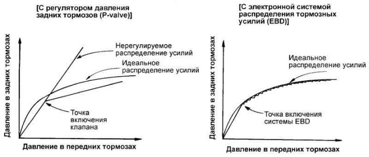
Fig. 6.57. Comparative characteristics of the distribution of braking forces
Comparative characteristics of the distribution of braking forces are presented in Fig. 6.57.
Checking the hydraulic and electronic control unit of ABS
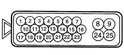
Fig. 6.58. ABS electronic control unit connector
See Fig. 6.58.
ABS Electronic Control Unit (HECU) Input/Output Wiring Diagram
(The article is copied from this website HyundaiBook.ru)
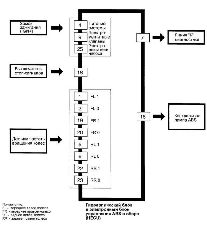
Fig. 6.59. Input/output diagram of the ABS electronic control unit
The input-output diagram of the ABS electronic control unit is shown in Fig. 6.59.