
Contents: EBD (Electronic Brakeforce…⇓ Control lamps ⇓ Features of the ABS system ⇓ ABS brake fault codes ⇓ Addressing the contacts of the…⇓ ABS hydroelectronic control unit…⇓ Bleeding the brake hydraulic system ⇓
The anti-lock braking system (ABS) controls the pressure in the hydraulic brake drive of each wheel individually and reduces the fluid pressure in the wheel brake mechanism whose wheel begins to lock.
ABS performs the following functions:
- Improved vehicle control stability when avoiding obstacles even during braking.
- Reducing the braking distance during heavy braking while maintaining vehicle stability and control even when cornering.
The anti-lock braking system operates based on information from four sensors transmitted to the ABS unit. The system controls each wheel separately and reduces the fluid pressure in the wheel brake mechanism whose wheel begins to lock.
Under normal conditions, the standard brake system applies the brakes until the wheel locks up, which is detected by the ABS control unit. When the ABS control unit detects a wheel lock up, it controls each valve to increase or decrease the pressure.
The ABS control unit determines the rotation speed and deceleration rate of each wheel based on information from the wheel speed sensors. When braking, the wheel speed decreases and the ABS unit determines the difference between the vehicle speed and the wheel speed. If the deceleration of some wheels exceeds the expected value, the ABS unit determines the onset of locking and opens the corresponding electromagnetic valves to reduce the brake fluid pressure. At the same time, the wheel speed increases and the electromagnetic pressure relief valve closes, increasing the brake fluid pressure in the working brake cylinder of the corresponding wheel.
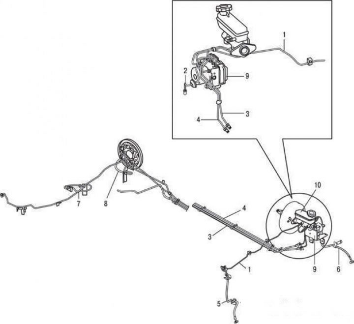
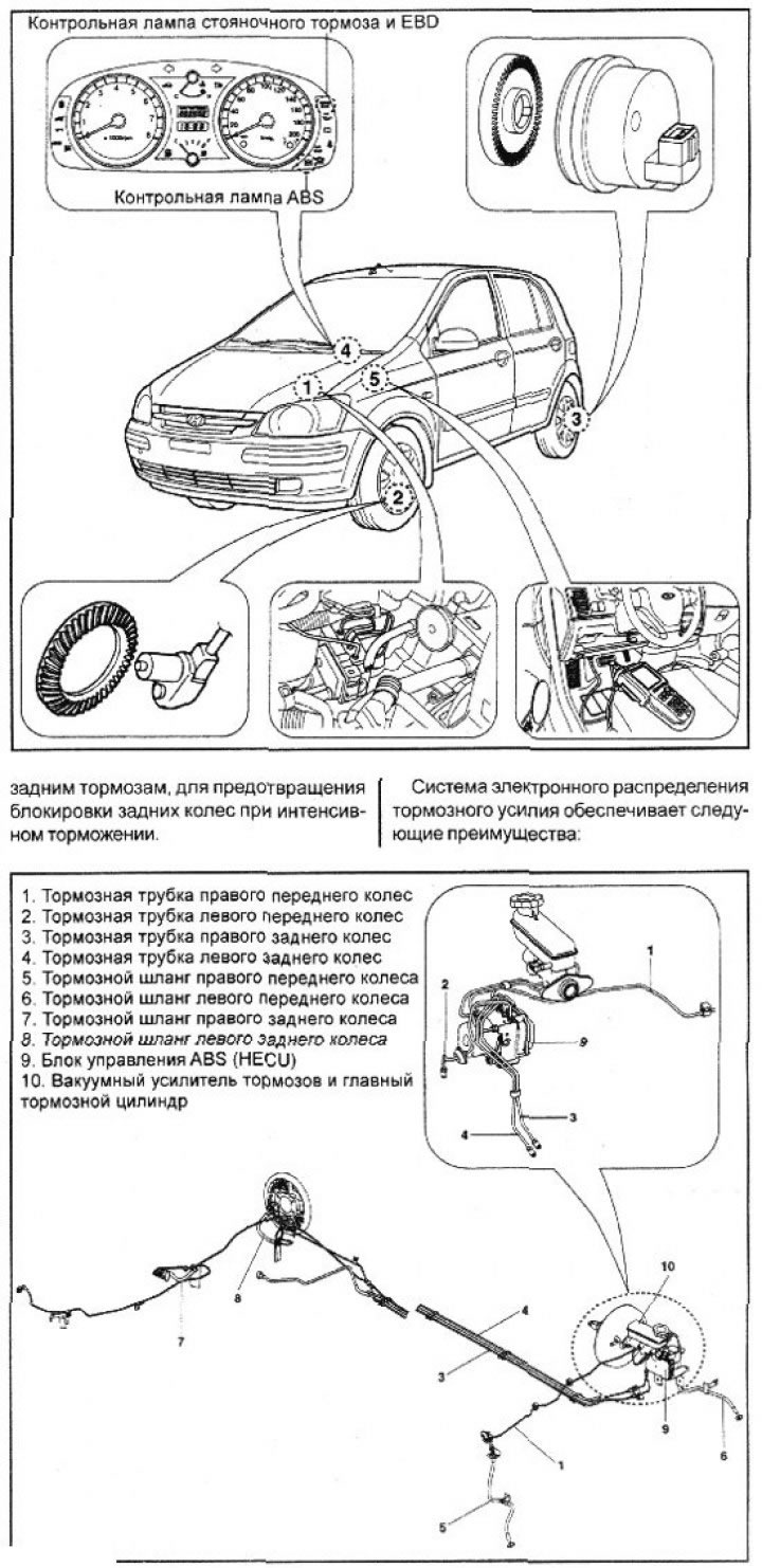
ABS hydraulic system: 1 – brake pipe of the right front wheel; 2 – brake pipe of the left front wheel; 3 – brake pipe of the right rear wheel; 4 – brake pipe of the left rear wheel; 5 – brake hose of the right front wheel; 6 – left front wheel brake hose; 7 – brake hose of the right rear wheel; 8 – left rear wheel brake hose; 9 – ABS hydroelectronic control unit (HECU); 10 – brake booster and master cylinder
EBD (Electronic Brakeforce Distribution)
EBD is additionally used instead of the pressure regulator to ideally distribute the pressure to the front and rear brakes.
- improving the performance of the basic braking system;
- compensation of friction coefficient differences;
- abolition of pressure regulator;
- malfunction signaling by control lamp.
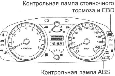
Control lamps
The ABS indicator light shows the level of ABS performance.
The ABS warning light comes on in the following cases:
- within 3 s after ignition is turned on;
- in case of ABS operation prohibition due to malfunction;
- if the ECU does not turn on when the ignition is on;
- in diagnostic mode.
The EBD indicator light indicates the EBD operating status.
The EBD indicator light comes on in the following cases:
- during initialization after ignition is turned on (3 s);
- in case of EBD operation prohibition due to malfunction;
- if the ECU does not turn on when the ignition is on;
- when the parking brake is applied or the brake fluid level is low.
Features of the ABS system
Sound when checking the ABS system. When starting the engine, a dull knock is sometimes heard from the engine compartment. It is associated with checking the operability of the system.
Sound during ABS operation. Sound of ABS hydraulic unit electric motor operation (howling sound). Scratching sound accompanied by brake pedal vibration.
When ABS is active, sounds are emitted from the vehicle chassis, which are caused by repeated cycles of braking and releasing the wheels (thuds coming from the suspension; (squeak of tires).
Long braking distance. On some road surfaces, including snowy roads or gravel surfaces, the braking distance of vehicles equipped with ABS may be longer than usual. Therefore, when driving on such roads, the vehicle owner must exercise caution and drive at a reduced speed.
Brake pedal vibration is normal.
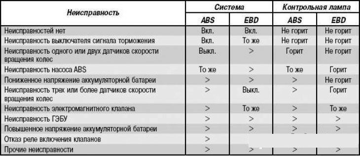
ABS brake fault codes
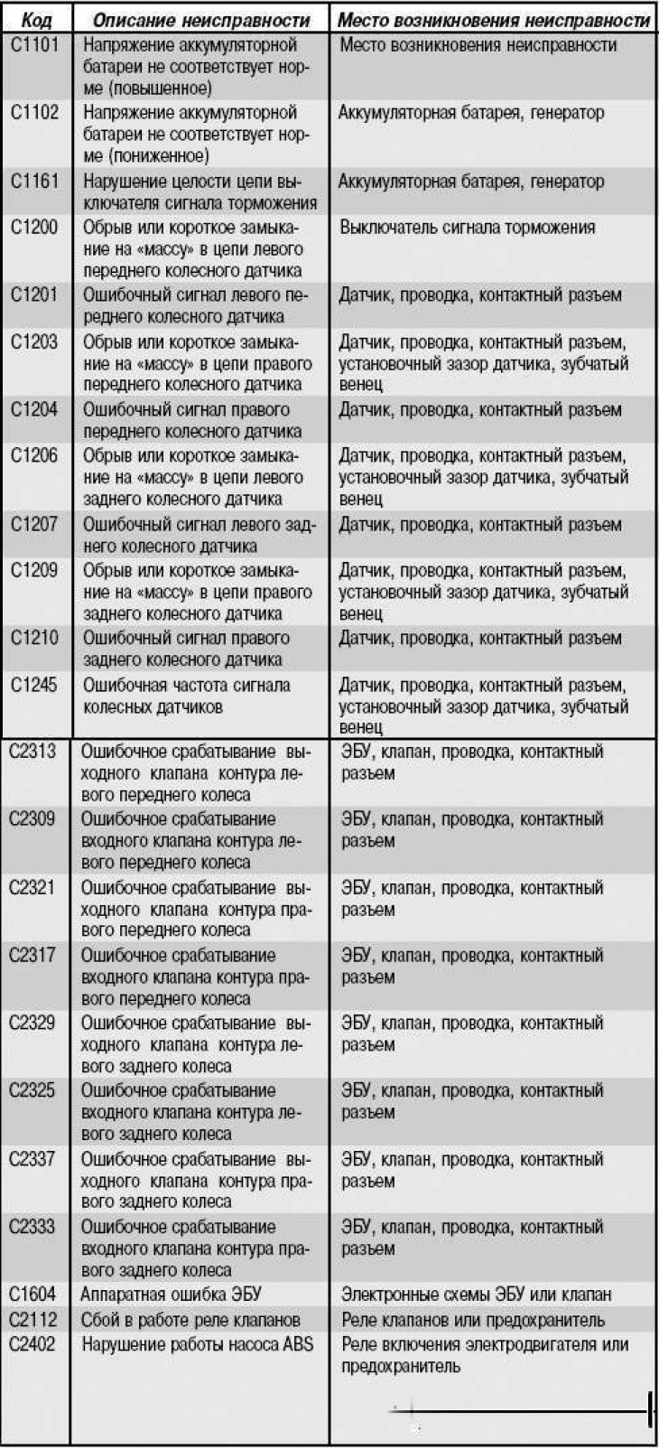
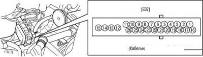
Cable part of the ABS electronic control unit connector
The cable part of the ABS electronic control unit connector is shown in the figure. The addressing of the cable part of the ABS electronic control unit connector is given in the table.
Addressing the contacts of the connector of the hydraulic electronic control unit (GECU) of the ABS system
| Number contacts | Address (contact purpose) | Maximum current strength | Minimum current strength | Note |
| 1 | - | - | - | |
| 2 | - | - | - | |
| 3 | - | - | - | |
| 4 | EBD warning light | 30 mA | 5 mA | |
| 5 | Diagnostic interface | 6 mA | 3 mA | |
| 6 | Right front wheel sensor | 16 mA | 6 mA | |
| 7 | Right front wheel sensor | 16 mA | 6 mA | |
| 8 | Right rear wheel sensor | 16 mA | 6 mA | |
| 9 | - | - | - | |
| 10 | Left rear wheel sensor | 16 mA | 6 mA | |
| 11 | Left front wheel sensor | 16 mA | 6 mA | |
| 12 | "Weight" | 5-15 A | 2.5 A | ABS control |
| 13 | Voltage a/b 1 (power supply for valves) | 5-15 A | 2 A | ABS control |
| 14 | Voltage a/b 2 (electric motor power supply) | 20-39 A | 10 A | ABS control |
| 15 | "Weight" | 20-39 A | 10 A | ABS control |
| 16 | - | - | - | |
| 17 | - | - | - | |
| 18 | - | - | - | |
| 19 | - | - | - | |
| 20 | ABS warning light | 30 mA | 5 mA | |
| 21 | - | | | |
| 22 | Brake light switch | 10 mA | 5 mA | |
| 23 | Right rear wheel sensor | 16 mA | 6 mA | |
| 24 | Ignition | 1 A | 500 mA | |
| 25 | Left rear wheel sensor | 16 mA | 6 mA | |
| 26 | Left front wheel sensor | 16 mA | 6 mA | |
ABS hydroelectronic control unit (HECU)
Removal
Remove the air filter and air intake pipe.
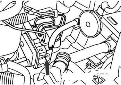
GEBU contact connector
Disconnect the ECU double-lock connector by pulling it upwards.
Disconnect the brake lines from the ECU.
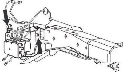
ECU bracket mounting bolts (indicated by arrows)
Loosen the ECU bracket mounting bolts and remove the ECU.
The tightening torque of the ECU bracket mounting bolts is 8–10 N·m.
Attention!
- Disassembly of the ECU is not permitted.
- Transportation and storage of the GEBU in a vertical position with plugged holes is permitted.
- Do not drain the fluid from the ECU.
Installation
Install the ECU in the reverse order of removal.
Tighten the ECU mounting bolts to a torque of 8–10 N·m, and the brake pipe mounting fittings to a torque of 13–17 N·m.
Checking the signal voltage of the wheel sensors
Place the car on a lift, release the parking brake.
Disconnect the ECU connector and perform a check on the contacts of the cable portion of the connector.
Note: When checking, remove the double lock of the contact connector and connect the test device to the wires on the side opposite the connector contacts. Connecting the test probes of the device to the contacts themselves does not ensure a reliable connection
Using a tester or oscilloscope, check the signal voltage of the wheel sensors by rotating the corresponding wheel at a speed of 0.5–1 s⁻¹.
Connecting a control device to check the signal voltage of wheel sensors
| Wheel sensor | Connector pin numbers |
| Left front | 11, 26 |
| Right front | 6, 7 |
| Left rear | 10, 25 |
| Right rear | 8, 23 |
Signal voltage when measured with an oscilloscope, V:
- lower level - 0.535 (at current of 7 mA)
- upper level - 1.050 (at 14 mA current)
Wheel speed sensors
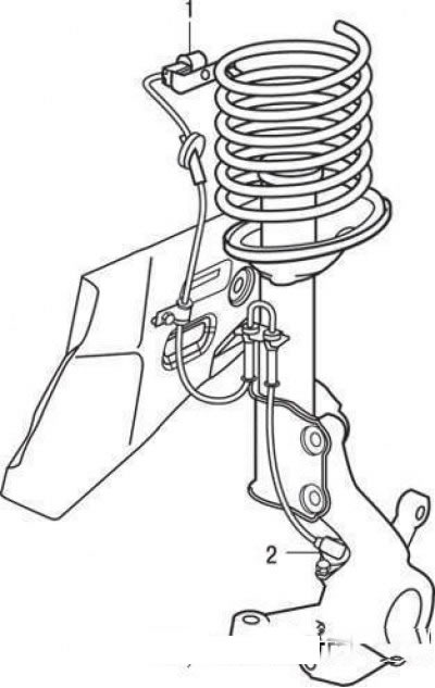
Front Wheel Speed Sensor: 1-pin connector for front wheel speed sensor; 2 – front wheel speed sensor
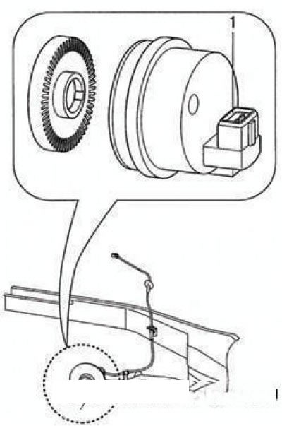
Rear wheel speed sensor: 1 – rear wheel speed sensor
Removal the front wheel sensor
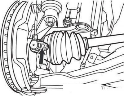
Front wheel sensor mounting bolt
Loosen the front wheel sensor mounting bolt.
In the engine compartment, disconnect the front wheel sensor connector.
Remove the wheel sensor wiring fasteners.
Remove the wheel sensor.
Removal the rear wheel sensor
Disconnect the rear wheel sensor connector from the wheel hub.
Remove the brake drum by unscrewing the screw that secures it to the wheel hub.
Remove the four bolts securing the rear wheel hub to the rear suspension beam.
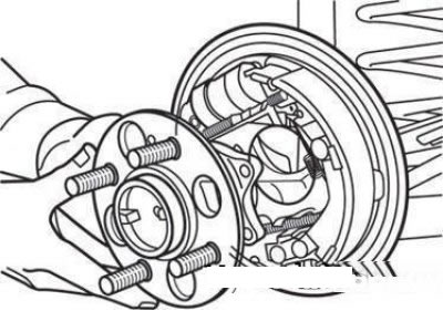
Removing the rear wheel hub
Remove the rear wheel hub through the brake mechanism.
Caution! Do not remove the wheel sensor from the hub by hammering, as this may cause the sensor to fail.
Bleeding the brake hydraulic system
The operation is carried out to effectively remove air from the brake hydraulic drive and fill the hydraulic unit of the anti-lock brake system, brake lines and the master brake cylinder with brake fluid.
To remove air from the hydraulic brake system of vehicles equipped with an anti-lock braking system, the HI-SCAN diagnostic device is used. During this operation, the device, connected to the diagnostic connector under the instrument panel, controls the electromagnetic valves and the electric pump of the anti-lock braking system.
Remove the brake fluid reservoir cap and fill the reservoir with brake fluid.
When topping up, use only DOT-3 or DOT-4 brake fluid.
Caution! If brake fluid gets on the paintwork of the car body, wash it off immediately with plenty of water.
Note: When using the special air bleeding device, do not press the brake pedal.
Attach a clear plastic hose to the bleeder nipple on the wheel cylinder and place the other end of the hose in a clear container half filled with brake fluid.
Connect the HI-SCAN tool to the diagnostic connector located under the instrument panel.
Using the HI-SCAN device, turn on the electric pump and the electromagnetic valves of the anti-lock braking system.
Perform the operations according to the instructions displayed on the HI-SCAN screen.
Caution! To prevent burnout of the windings of the anti-lock braking system pump electric motor, do not exceed the maximum permissible operating time indicated on the HI-SCAN device screen.
Press the brake pedal several times, opening the bleeder screw until no more air bubbles appear in the fluid flowing out, then tighten the bleeder screw.
Perform the described operation on the remaining wheels of the vehicle in the following order: rear right wheel (in the direction of vehicle travel), front left wheel, rear left wheel, front right wheel.
Tightening torque of bleed nipples: 7–13 Nm.