
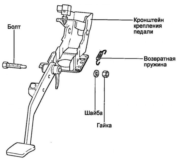
Fig. 6.7. Brake pedal
Removal
Remove the brake light switch.
Remove the cotter pin and pull out the tie rod pin.
Loosen the brake pedal bracket mounting nuts.
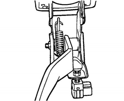
Fig. 6.8. Pedal assembly with bracket
Remove the bracket together with the brake pedal (Fig. 6.8).
Examination
Assess the degree of wear on the pedal bushings.
Make sure there is no deformation of the pedal.
Check the return spring.
Check the brake light switch.
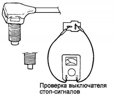
Fig. 6.9. Measuring the resistance between the switch terminals
Using an ohmmeter, measure the resistance between the switch terminals (Fig. 6.9).
If the circuit is open when the switch pusher is pressed (infinite resistance), and there is one when the pusher is released (zero resistance), the switch is normal.
Installation
Installation is carried out in reverse order.
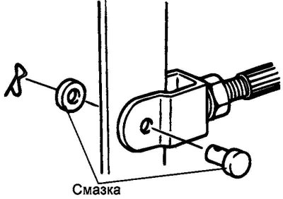
Fig. 6.10. Fixing the earring finger with a pin
Note: Don't forget to secure the earring pin with a pin (Fig. 6.10).
Tighten the pedal bracket mounting nuts to the specified torque of 13–16 N·m.
Adjust the pedal height and free play.
Install the brake light switch.