
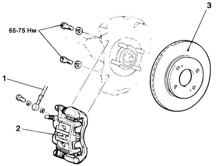
Fig. 6.18. Front disc brake: 1 – connecting tube (brake hose and tube assembly); 2 – front brake caliper assembly; 3 – brake disc
Removal
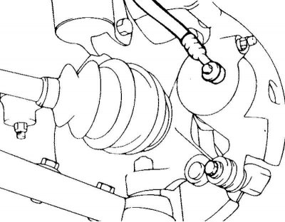
Fig. 6.19. Caliper mounting bolt
Unscrew the lower caliper bolt, lift it up and secure it with wire (Fig. 6.19).
Remove the brake pads.
Caution: Do not press the brake pedal when the brake pads are removed.
Examination
Measure the thickness of the friction layer of the pad. Make sure that the pad is not oiled.
Caution! Always replace brake pads of one axle at the same time. Do not install pads of different types and manufacturers.
All four pads are replaced as a set.
When replacing the pads, check that they are not deformed. When replacing the spring, carefully remove all dirt.
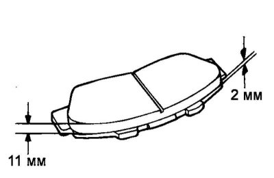
Fig. 6.20. Brake pads
Check the old pads for deformation and destruction (Fig. 6.20).
Thickness of the pad:
- Nominal: 11 mm
- Limit: 2 mm
Installation
Install the pads into the spring guides.
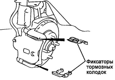
Fig. 6.21. Brake shoe retainers
Install the brake shoe retainers (Fig. 6.21).
Note: The pad wear indicator should point upwards towards the piston.
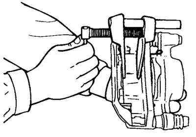
Fig. 6.22. Installing the piston in the caliper
Using a special tool (09581-11000) insert the pistons into the caliper (Fig. 6.22).
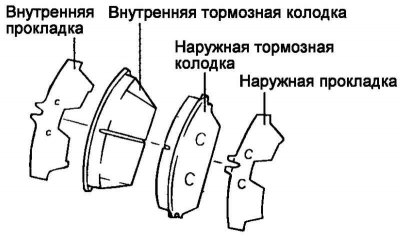
Fig. 6.23. Brake pad components
Install the pads with gaskets as shown in Figure 6.23.
Caution! Do not allow grease to come into contact with the pads and brake disc.
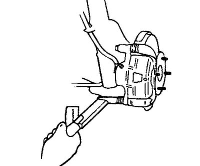
Fig. 6.24. Installing the lower (guide) caliper bolt
Install the lower (guide) bolt of the caliper and tighten it to the specified torque (Fig. 6.24).
Tightening torque 22–32 Nm.