
Unscrew the bolt securing the brake hose to the caliper.
Loosen the caliper cylinder mounting bolts.
Remove the cylinder and brake pads.
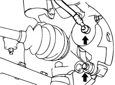
Fig. 6.25. Bolts for fastening the caliper to the steering knuckle
Loosen the bolts securing the caliper to the steering knuckle (Fig. 6.25).
Remove the caliper.
Disassembly
Remove the piston dust boot.
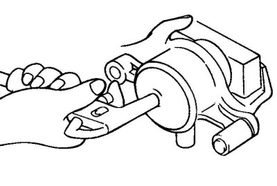
Fig. 6.26. Removing the piston from the caliper
Using compressed air, push the piston out of the caliper (Fig. 6.26).
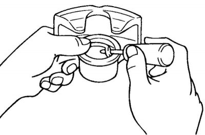
Fig. 6.27. Removing the piston seal
Using a screwdriver, remove the piston seal from the caliper (Fig. 6.27).
Note: Do not place your fingers between the piston and the caliper.
Note: Be careful not to splash the brake fluid.
Examination
Check the caliper for wear, cracks, and rust in the piston holes.
Assess the condition of the pistons. If worn or scuffed, replace the piston.
Check the condition of the bushing and pin.
Make sure there is no damage to the brake shoe springs and piston dust boots.
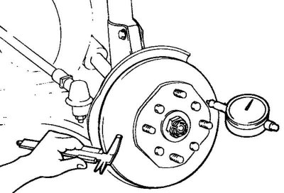
Fig. 6.28. Measuring the thickness and runout of the brake disc
Measure the thickness and runout of the brake disc (Fig. 6.28).
Caution! Do not restore the piston surface with sandpaper.
Caution: All rubber parts cannot be reinstalled.
Brake disc thickness:
- Nominal: 24 mm.
- Limit: 22.4 mm.
- Disc runout: 0.08 mm, no more.
- Brake disc thickness difference: 0.01mm.
Note: The difference in brake disc thickness is determined by the difference between the minimum and maximum thicknesses measured at eight points around the circumference approximately 10 mm from the edge of the disc.
The disc runout is determined by the circumference 5 mm from the edge of the disc.
If repair is not possible, replace the brake disc.
Assembly
Wash all parts (except pads and pad gaskets) with isopropyl alcohol.
Lubricate the piston seal with special grease and install the seal into the groove of the caliper bore.
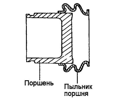
Fig. 6.29. Piston and dust cover
Install the piston and its dust cover (Fig. 6.29).
Lubricate the caliper bore under the piston, the outer surface of the piston and the dust boot with special grease.
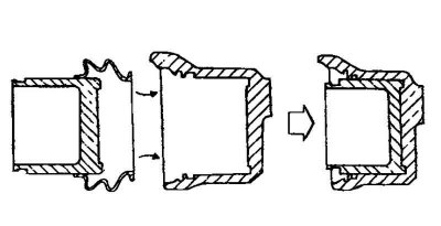
Fig. 6.30. Piston and dust cover installation diagram
Install the dust boot on the piston as shown in Figure 6.30.
Insert the dust boot into the caliper bore groove and push the piston into the caliper.
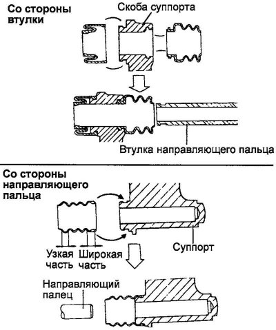
Fig. 6.31. Assembly diagram of the sliding parts of the caliper
Assemble the sliding parts of the caliper (Fig. 6.31).
Lubricate the bushing, pin and the caliper hole for the bushing with special grease. Also lubricate the bushing and pin dust boots.
Install the dust boot into the caliper bore groove.
Install the brake pads.
Note: Avoid getting grease on the pads and brake disc.
(The material was obtained from a web resource hyundaibook.ru)
Note: Before tightening the bolts, make sure that the surfaces of the sliding pin and guide bolt are not damaged.
Note: Bleed the brake system. Make sure there are no brake fluid leaks.