
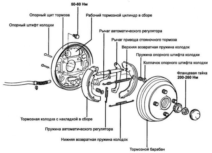
Fig. 6.42. Rear drum brakes
Removal
Remove the rear wheel.
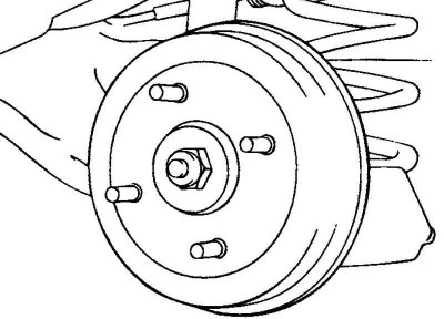
Fig. 6.43. Rear wheel hub
Loosen the mounting nut and remove the hub together with the brake drum (Fig. 6.43).
Remove the lower return spring and the shoe retaining springs.
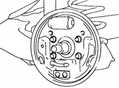
Fig. 6.44. Brake pads and adjuster assembly
Remove the brake pads and adjuster assembly (Fig. 6.44).
Examination

Fig. 6.45. Measuring the thickness of brake pads
Measure the thickness of the brake pads (Fig. 6.45).
Nominal pad thickness: 5.14 mm.
Maximum pad thickness: 1.5 mm.
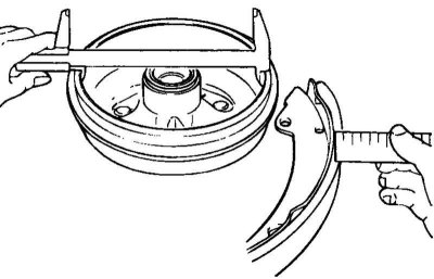
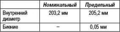
Fig. 6.46. Measuring the inner diameter of the brake drum
Measure the inner diameter of the brake drum (Fig. 6.46).
Check the brake drum runout.
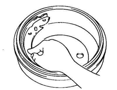
Fig. 6.47. Checking the completeness of the fit of the brake shoes and drum
Check the complete contact between the shoe and the brake drum (Fig. 6.47).
Inner diameter and maximum runout of the brake drum
Installation
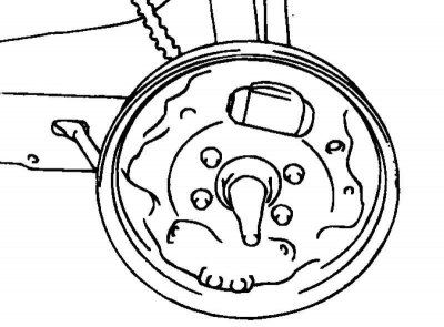
Fig. 6.48. Lubrication application areas
Apply special grease to the places indicated in the figure (Fig. 6.48).
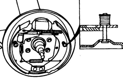
Fig. 6.49. Installation diagram of the locking spring
Install the pin and spring for fixing the brake shoe (Fig. 6.49).
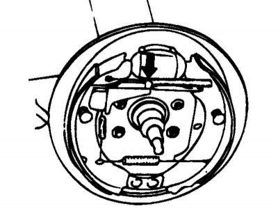
Fig. 6.50. Installing the upper return spring
Press the rod and install the upper return spring (Fig. 6.50).
After assembly, press the parking brake lever several times.