


Car automatic transmission Hyundai Elantra 3

Technical data of automatic transmission
Name A4AF3 F4A42 Torque converter type 3 elements, 1 stage, 2 phases Type of transmission 4 forward gears and 1 reverse gear Engine displacement 1,6 D 1,8/ 2,0 D Gear...
Name A4AF3 F4A42 Torque converter type 3 elements, 1 stage, 2 phases Type of transmission 4 forward gears and 1 reverse gear Engine displacement 1,6 D 1,8/ 2,0 D Gear...

Checking the fluid level in the automatic transmission
Warning! The vehicle must be parked on a level, horizontal surface. Procedure 1. Drive until the gearbox warms up to 70–80°C. 2. Park the car on a level horizontal...
Warning! The vehicle must be parked on a level, horizontal surface. Procedure 1. Drive until the gearbox warms up to 70–80°C. 2. Park the car on a level horizontal...

Automatic transmission fluid replacement
If the torque converter fluid is being replaced, also replace the transmission fluid. If the torque converter fluid is not being replaced, replace the transmission fluid...
If the torque converter fluid is being replaced, also replace the transmission fluid. If the torque converter fluid is not being replaced, replace the transmission fluid...

Checking the transmission range switch conductivity (F4A42)
Disconnect the connector and check the transmission range switch for continuity at different selector lever positions.
Disconnect the connector and check the transmission range switch for continuity at different selector lever positions.

Gearbox Range Switch and Control Cable Adjustment (F4A42)
Procedure 1. Set the selector lever to the "N" position. 2. On the gearbox side, loosen the nut securing the control cable to the lever to release the cable and control...
Procedure 1. Set the selector lever to the "N" position. 2. On the gearbox side, loosen the nut securing the control cable to the lever to release the cable and control...
Checking the operation of the selector lever (A4AF3)
Procedure 1. Move the selector lever to all positions. Check that the position of the selector lever matches the selector lever indicator. 2. Start the engine and check...
Procedure 1. Move the selector lever to all positions. Check that the position of the selector lever matches the selector lever indicator. 2. Start the engine and check...

Adjusting the selector lever position indicator switch (A4AF3)
Procedure 1. Move the selector lever to position N. 2. Loosen the control lever lock nut where the cable and lever connect. 3. Move the control lever to the N position....
Procedure 1. Move the selector lever to position N. 2. Loosen the control lever lock nut where the cable and lever connect. 3. Move the control lever to the N position....

Automatic Transmission Component Check (F4A42)
Checking the throttle position sensor The throttle position sensor is a variable resistor that rotates with the throttle shaft and provides information to the ECM to...
Checking the throttle position sensor The throttle position sensor is a variable resistor that rotates with the throttle shaft and provides information to the ECM to...
Testing the combined operation of the automatic transmission and engine on a stationary vehicle (F4A42)
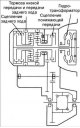
Testing is performed to determine the maximum engine speed when the selector lever is in the "D" or "R" positions, and to check the operation of the torque converter,...
Testing is performed to determine the maximum engine speed when the selector lever is in the "D" or "R" positions, and to check the operation of the torque converter,...

Checking Transmission Fluid Pressure (F4A42)
A transmission fluid pressure test is performed to determine the condition of the hydraulic components and whether there are any leaks. Procedure 1. Start the engine...
A transmission fluid pressure test is performed to determine the condition of the hydraulic components and whether there are any leaks. Procedure 1. Start the engine...

Checking the transmission fluid pressure (A4AF3)
Procedure 1. Start the engine until the gearbox warms up. 2. Raise the front of the vehicle so that the drive wheels can turn freely. 3. Connect the tachometer and...
Procedure 1. Start the engine until the gearbox warms up. 2. Raise the front of the vehicle so that the drive wheels can turn freely. 3. Connect the tachometer and...
Diagnostic function
Procedure 1. Connect the HI–SCAN scanner to the diagnostic connector. 2. Read the fault codes. The memory (RAM) can store 8 fault codes in the order they appear. The...
Procedure 1. Connect the HI–SCAN scanner to the diagnostic connector. 2. Read the fault codes. The memory (RAM) can store 8 fault codes in the order they appear. The...
Diagnostic codes
Diagnostic codes (F4A42) Code Malfunction P1704 Short circuit in the electrical circuit of the throttle position sensor P1703 Open circuit of the throttle position...
Diagnostic codes (F4A42) Code Malfunction P1704 Short circuit in the electrical circuit of the throttle position sensor P1703 Open circuit of the throttle position...

Adjusting the axial clearance of the reaction brake (F4A42)
Fix the low and reverse brake pressure plate with the special tool and install the brake disc and spring ring as shown in the figure. Install the reaction plate and snap...
Fix the low and reverse brake pressure plate with the special tool and install the brake disc and spring ring as shown in the figure. Install the reaction plate and snap...

Adjusting the axial clearance of the second gear brake (F4A42)
Secure the second brake pressure plate with a special tool and then install the brake disc as shown in the figure. Install the return spring, second gear brake piston...
Secure the second brake pressure plate with a special tool and then install the brake disc as shown in the figure. Install the return spring, second gear brake piston...

Adjusting the Low and Reverse Brake Axial Clearance (F4A42)
Engage reverse gear and measure the gap. To measure the axial clearance, move the special tool up and down. Axial clearance: 1.35–1.81 mm. Select a pressure plate whose...
Engage reverse gear and measure the gap. To measure the axial clearance, move the special tool up and down. Axial clearance: 1.35–1.81 mm. Select a pressure plate whose...

Adjusting the axial clearance of the underdrive sun gear (F4A42)
Install the thrust bearing ring *8 and rear cover. Measure the axial clearance of the underdrive sun gear. Replace thrust bearing ring *8 to adjust clearance to standard...
Install the thrust bearing ring *8 and rear cover. Measure the axial clearance of the underdrive sun gear. Replace thrust bearing ring *8 to adjust clearance to standard...

Differential Preload Adjustment (F4A42)
Place the solder (approximately 10mm long, 3mm in diameter) on the torque converter housing as shown in the figure. Install the torque converter housing to the...
Place the solder (approximately 10mm long, 3mm in diameter) on the torque converter housing as shown in the figure. Install the torque converter housing to the...
Elements of the hydraulic control system
General information 1. The hydraulic transmission control system consists of the following units: 1) Oil pump: creates hydraulic pressure. 2) Regulator: maintains...
General information 1. The hydraulic transmission control system consists of the following units: 1) Oil pump: creates hydraulic pressure. 2) Regulator: maintains...

Identification of bearings of automatic transmission F4A42
Identification of bearings of automatic transmission F4A42
Identification of bearings of automatic transmission F4A42
Malfunction Indicator Lamp (MIL)
The MIL indicator lamp comes on when there are malfunctions in the engine management system and automatic transmission. However, the MIL will not illuminate after three...
The MIL indicator lamp comes on when there are malfunctions in the engine management system and automatic transmission. However, the MIL will not illuminate after three...

Identification of bearings of automatic transmission F4A43
Identification of bearings of automatic transmission F4A43
Identification of bearings of automatic transmission F4A43

Adjusting the forced downshift servo (A4AF3)
Procedure 1. Clean all dirt from the downshift servo adjustment screw. 2. Loosen the locknut. 3. Loosen and tighten the adjustment screw twice to a tightening torque of...
Procedure 1. Clean all dirt from the downshift servo adjustment screw. 2. Loosen the locknut. 3. Loosen and tighten the adjustment screw twice to a tightening torque of...

Adjusting the pressure in the line (A4AF3)
Procedure 1. Drain the transmission fluid from the automatic transmission. 2. Remove the oil pan. 3. Remove the oil filter. 4. Remove the transmission fluid temperature...
Procedure 1. Drain the transmission fluid from the automatic transmission. 2. Remove the oil pan. 3. Remove the oil filter. 4. Remove the transmission fluid temperature...
Replacing the drive shaft oil seal ring
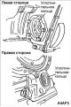
Procedure 1. Disconnect the drive shaft from the gearbox. 2. Using a flat-head screwdriver, remove the sealing ring from the gearbox socket. 3. Using drift 09431–21200,...
Procedure 1. Disconnect the drive shaft from the gearbox. 2. Using a flat-head screwdriver, remove the sealing ring from the gearbox socket. 3. Using drift 09431–21200,...

Removal and installation of the F4A42 gearbox
Removal 1. First, disconnect the wire from the negative terminal of the battery, then from the positive one. Remove the battery and battery support. 2. Remove the drain...
Removal 1. First, disconnect the wire from the negative terminal of the battery, then from the positive one. Remove the battery and battery support. 2. Remove the drain...

Removal and installation of gearbox A4AF3
Removal 1. Remove the drain plug and drain the transmission oil from the gearbox into a suitable container. 2. Remove the air filter. 3. Disconnect the connector from...
Removal 1. Remove the drain plug and drain the transmission oil from the gearbox into a suitable container. 2. Remove the air filter. 3. Disconnect the connector from...
Automatic transmission control
Examination 1. Check the retainer for wear. 2. Check the bushing for wear or damage. 3. Check the spring for damage and loss of elasticity. 4. Check the cam at the end...
Examination 1. Check the retainer for wear. 2. Check the bushing for wear or damage. 3. Check the spring for damage and loss of elasticity. 4. Check the cam at the end...

Installing a blocking device
Attention! To ensure normal operation, when servicing the locking device, follow the operating rules and recommendations given below. Installing the lock cam 1. Manually...
Attention! To ensure normal operation, when servicing the locking device, follow the operating rules and recommendations given below. Installing the lock cam 1. Manually...

Installing a key lock device
It is expected that the ignition key cannot be removed from the lock cylinder until the lock cable is disconnected from the lock. To avoid these problems during repair...
It is expected that the ignition key cannot be removed from the lock cylinder until the lock cable is disconnected from the lock. To avoid these problems during repair...
This section is available on russian, bulgarian, belarusian, ukrainian, serbian, croatian, romanian, polish, slovak, hungarian
We recommend other sections on the topic of Hyundai manuals:
Transmission: Automatic gearbox Hyundai Accent 2 (1999-2005)
Transmission: Automatic gearbox Hyundai Getz (2002-2011)
Transmission: Automatic gearbox Hyundai Sonata 4 (2001-2012, petrol)
Transmission: Automatic gearbox Hyundai Santa Fe 2 (2007-2012, petrol)
Transmission: Automatic gearbox Hyundai Tucson 2 (2009-2015)
Transmission: Automatic gearbox Hyundai Matrix (2001-2010, petrol)
Link in different formats to this section
TextHTMLBB Code
- User manual
- Control devices
- Audio system
- Starting the engine and driving
- Faults en route
- Maintenance and care
- Technical information
- Power unit
- Gasoline engines
- Diesel engines
- Lubrication system
- Cooling system
- Fuel system (gasoline)
- Fuel system (diesel)
- Decreased toxicity
- Ignition system
- Transmission
- Clutch
- Mechanical gearbox
- Automatic gearbox
- Drive shafts and axles
- Chassis
- Car suspension
- Steering
- Brake system
- Body
- Exterior (external elements)
- Interior (internal elements)
- Air conditioning system
- Electrical equipment
- Equipment and devices
- Headlights and lighting
- Power devices
- Electrical circuits
- General information
- Maintenance
- Power unit
- Engine repair
- Cooling system
- Intake and exhaust system
- Fuel system
- Transmission
- Clutch
- Manual gearbox
- Automatic gearbox
- Drive shafts and axles
- Chassis
- Front suspension
- Rear suspension
- Steering
- Brake system
- Body
- Body elements
- Electrical equipment
- Equipment and devices
- Electrical diagrams
- General information
- Introduction to the guide
- Maintenance
- Power unit
- Minor engine repair
- Engine overhaul
- Lubrication system
- Cooling system
- Fuel injection system
- Ignition system
- Exhaust system
- Transmission
- Clutch
- Manual gearbox
- Automatic gearbox
- Drive shafts
- Chassis
- Front suspension
- Rear suspension
- Steering
- Wheels and tires
- Troubleshooting
- Brake system
- Body
- Body elements
- Electrical equipment
- Equipment and devices
- Power devices
- Heating and air conditioning
- Electrical circuits