
Contents: Installing the lock cam ⇓ Adjusting the travel and locking…⇓ Checking the correct installation of…⇓ Precautionary measures ⇓
Attention! To ensure normal operation, when servicing the locking device, follow the operating rules and recommendations given below.
Installing the lock cam
1. Manually move the closing cam in direction "A".
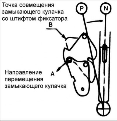
2. Make sure the locking cam is aligned at point "B" with the locking pin.
Adjusting the travel and locking cables
1. Check that each lock cam is in the position shown in the figure.
2. In this position, install the travel cable and wedge the lock cable. In this case, the locking cable should connect to the brake pedal in the original position of the pedal.
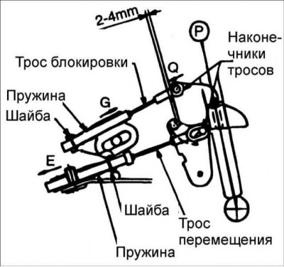
3. Temporarily connect each cable to the lever on the automatic transmission as shown. Insert the cable securely into the installation pin of each cam.
4. By moving the locking cable slightly in the "E" direction, remove the slack in the cable and ensure a clearance of 2-4 mm.
Caution! If the gap is not 2–4 mm, the brake pedal will have to be pressed much more than necessary for the lock button on the selector lever to function.
(The original source of the article is the website: hyundaibook)
5. After checking, make sure that the cable end touches the locking pin of the P-shaped locking cam, then move the locking cable end with the washer and fix it with the pin.
6. Press the locking cam lightly in the "Q" direction.
7. After performing step "f", slightly pull the locking cable in direction "G" until the slack is eliminated and secure it with the nut.
8. Make sure to check whether the lock cable is inserted into the lock cam lock pin, then install the washer and lock pin. At the same time, check whether the P-shaped locking cam is aligned with the travel cable as shown in the figure.
Checking the correct installation of the travel cable
1. If the brake pedal is not depressed, the button on the selector lever in the "P" position will not work (the selector lever cannot be moved from the "P" position to any other position). The button on the selector lever can be used in positions other than "P".
2. If the brake pedal travel is 15–25 mm (with the selector lever in the "P" position), the button should operate without catching and the selector lever can move out of the "P" position.
3. If the brake pedal is not pressed, the selector lever may smoothly move to the "P" position from other positions.
4. The brake pedal should operate smoothly without grabbing in all positions.
5. After turning the ignition key to the "LOCK" position, the button should work even if the brake pedal is not pressed.
6. The ignition key cannot be turned to the "LOCK" position unless the selector lever is in the "P" position.
7. If the selector lever is in the "P" position, the key in the ignition switch must be turned to the "LOCK" position.
Precautionary measures
1. Slightly move the lock cable in the "E" direction to ensure a clearance of 2~4 mm between the lock cam and the P-shaped lock cam, then secure the cable with the nut. After this, make sure that the gap is within 2-4 mm.
Caution! If the gap is not 2–4 mm, the brake pedal will have to be pressed much more than necessary for the lock button on the selector lever to function.
2. Make sure that the slack in the locking cable is removed.
Caution! If the slack in the lock cable is not removed, it will not be possible to remove the key from the ignition lock cylinder and the selector lever will not be able to be moved from the "P" position to other positions, even though the key in the ignition switch is in the "LOCK" position.
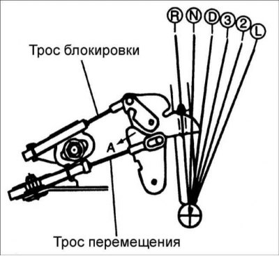
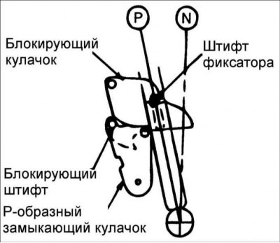
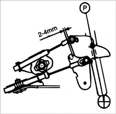
3. After completing all work, make sure that the locking cam and P-shaped closing cam are not in the positions shown in the figures.
Caution! If the locking cam and the P-shaped closing cam are in the positions shown in Figures 5 and 6, moving the selector lever from positions D, 3, 2, L to positions P, R, N with great force may result in damage to the interacting elements. If the cams are in the position shown in Fig. 5, move the selector lever from positions D, 3, 2, L to positions P, R, N after turning the P-shaped closing cam in direction "A".
Caution: If the cams are in the position shown in Fig. 6, move the selector lever from positions D, 3, 2, L to positions P, R, N after turning the P-shaped closing cam in direction "A" while depressing the brake pedal.