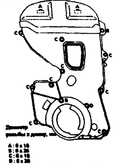
Contents: Self-tensioner ⇓ Installation ⇓
1. Check the camshaft and crankshaft gears, as well as the tension and guide rollers, for wear, cracks and damage. Replace them if necessary.
2. Check the ease and smoothness of rotation of the tension and guide rollers, as well as the presence of play and noise. Replace the rollers if necessary.
Self-tensioner
1. Check the tensioner for leaks and replace if necessary.
2. Check the end of the rod for wear and damage. Replace if necessary.
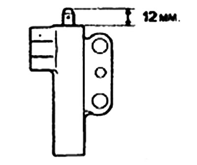
3. Measure the protruding length of the rod. If it differs from the nominal value, replace the tensioner.
- Nominal value: 12 mm.
4. Using a vice with small jaws, press the tensioner rod into the housing. If the rod comes out easily, replace the tensioner. Resistance should be felt when pressing the rod.
Warning.
- 1. When clamping the tensioner in a vice, make sure that it is in a horizontal position. To prevent damage to the tensioner, use soft pads on the jaws.
- 2. If the plug is located on the bottom of the tensioner housing, install a flat washer to prevent the plug from directly contacting the vise jaws.
Installation
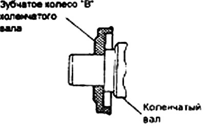
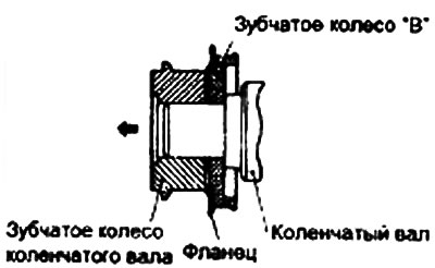
1. Install gear "B" on the crankshaft.
Warning: Pay particular attention to the location of the flange. Incorrect installation may cause the belt to break.
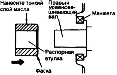
2. Apply a thin layer of engine oil to the outer surface of the spacer sleeve, then install the sleeve onto the right balance shaft. Make sure to install in the direction shown in the figure.
3. Install the balance shaft gear onto the right balance shaft and tighten the flange mounting bolts securely.
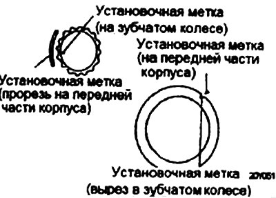
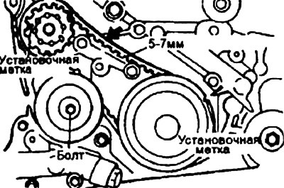
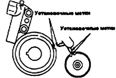
4. Align the timing marks on each gear with the corresponding marks on the front of the housing.
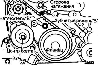
5. After installing the toothed belt "B", ensure that the tension is such that there is no slack in the belt. Install the tensioner "B" so that the pulley is aligned with the left mounting bolt and its flange is directed towards the front of the engine. Align the timing mark on the toothed wheel of the right balance shaft with the timing mark on the front of the housing.
Warning: Pay attention to the location. If it is not installed correctly, the belt may break.
6. Raise tensioner "B" to tension toothed belt "B" so that its working branch is taut. In this position, tighten the tensioner mounting bolt "B". When tightening the bolt, take measures to prevent the shaft from rotating with it. If the shaft turns, the belt will be overtightened.
7. Make sure that the alignment marks are aligned.
8. Check that when you press the center of the belt in the direction of the arrow with your index finger, the deflection does not exceed the value shown below.
- Belt deviation: 5-7 mm.
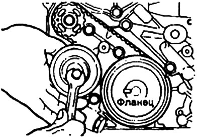
9. Install the flange and crankshaft gear onto the crankshaft. Make sure that the installation is as shown in the figure.
10. Install the special washer and gear bolt on the crankshaft, then tighten the gear bolt.
- The tightening torque of the crankshaft gear bolt is 110-130 Nm.
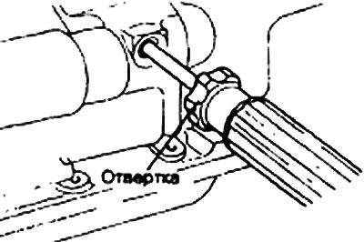
11. Insert a screwdriver into the plug hole on the left side of the cylinder block to hold the shaft in a certain position.
12. Install the oil pump gear and tighten the nut to the specified torque.
13. Install the camshaft timing gear and tighten the bolt to the specified torque.
- The tightening torque of the camshaft gear bolt is 80-100 Nm.
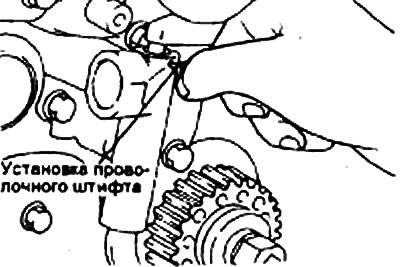
14. Install the self-tensioner.
Warning: Leave the wire pin installed in the tensioner.
Note.
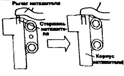
- If the tensioner rod is in the fully extended position, retract it as follows:
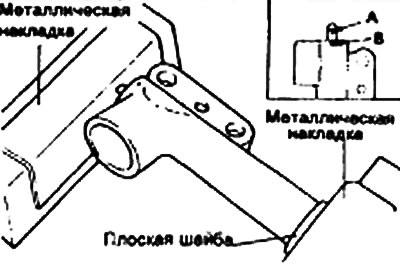
- 1. Clamp the tensioner in a vice with soft jaws, holding it horizontally. If the plug is located at the bottom of the tensioner, install a flat washer.
- 2. Slowly push the rod in with a vice until the mounting hole A of the rod is aligned with the mounting hole B of the cylinder.
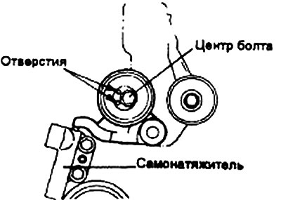
15. Install the tensioner pulley onto the tensioner arm. Position the holes in the end of the tensioner pulley shaft to the left of the center bolt and tighten the center bolt by hand.
Warning: Leave the wire pin installed in the tensioner.
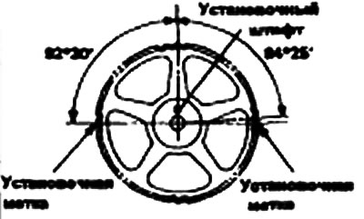
16. Turn the two gears so that their locating pins face up. Then align the locating marks.
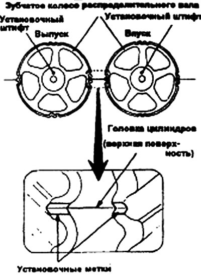
17. Align the timing marks on the gear and crankshaft.
18. Align the timing marks on the oil pump gear.
 |
 |
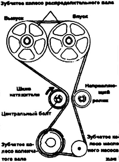
19. Install the timing belt on the tensioner pulley and crankshaft gear. Hold the timing belt on the tensioner pulley with your left hand.
20. Tighten the belt with your right hand and install it on the oil pump toothed wheel.
21. Install the belt on the guide roller.
22. Install the belt on the intake camshaft timing gear.
23. Turn the exhaust camshaft gear one tooth clockwise until its timing mark is aligned with the top row of the cylinder head. Then, tighten the belt with both hands and install it on the exhaust camshaft gear.
24. Carefully lift the tensioner pulley in the direction of the arrow so that the belt does not sag, and temporarily tighten the center bolt.
25. After turning the crankshaft 1/4 turn counterclockwise, turn it in the opposite direction to set the piston of the first cylinder to top dead center.
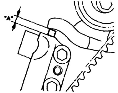
26. Loosen the central bolt and then use the special tool and torque wrench to tighten it to 2.6-2.8 Nm, as shown in the figure.
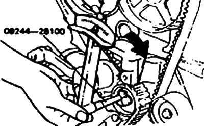
Note: Use a torque wrench with a torque of 0-3 Nm.
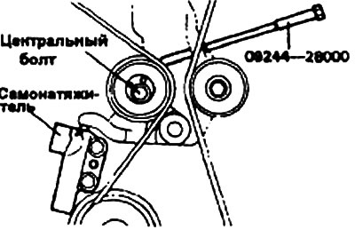
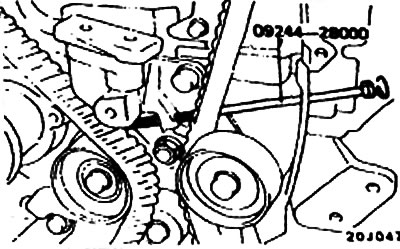
27. Hold the tensioner pulley with the special tool and torque wrench and tighten the center bolt to the specified torque. Screw the special tool into the left engine support bracket until its end contacts the tensioner arm. Then screw the special tool in a little more and remove the wire pin installed in the self-tensioner.
28. Remove the special tool.
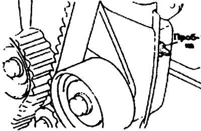
29. Turn the crankshaft two full turns clockwise and leave it in this position for about 15 minutes. Then measure the output "A" of the self-tensioner rod (the distance between the tensioner arm and its housing) to ensure that it corresponds to the nominal value.
- Nominal value: 3.8-4.5 mm
If the obtained value differs from the nominal value, repeat steps 25 through 29 until the required value is achieved.
Note: If it is not possible to measure the distance "A" between the tensioner arm and its housing (for example, if the engine is mounted on a vehicle), use the following alternative method.
- 1. Screw in the special tool until its end contacts the tensioner lever.
- 2. From this point on, screw in the special tool to push in the tensioner rod, counting the number of revolutions of the tool made until the tensioner lever touches its body. Make sure that the number of revolutions of the special tool made corresponds to the nominal value.
- Nominal value: 2.5-3 turns.
30. Install the rubber plug into the rear timing belt cover.
31. Install the lower and upper timing belt covers.