
Removal
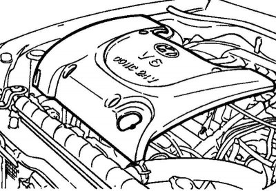
Fig. 2.207. Engine cover
Remove the engine cover (Fig. 2.207).
Using a 16 mm wrench, turn the automatic drive belt tensioner lever clockwise approximately 14 degrees and remove the belt.
Remove the power steering pump and crankshaft pulleys, tensioner pulley and idler pulley
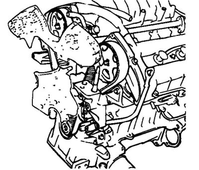
Fig. 2.208. Upper and lower timing belt covers
Remove the upper and lower timing belt covers (Fig. 2.208).
Remove the automatic timing belt tensioner.
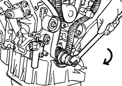
Fig. 2.209. Turning the crankshaft
Attention! Turn the crankshaft clockwise until the timing marks on the crankshaft sprocket and the block are aligned, corresponding to the TDC of the piston of the 1st cylinder (Fig. 2.209). The timing marks of the camshaft sprockets must be aligned with the benchmarks on the valve cover
Remove the timing belt.
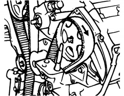
Fig. 2.210. Marking the direction of rotation
Note: If the timing belt is reused, it is necessary to mark with chalk on the reverse (non-working) surface of the belt an arrow indicating the direction of rotation (or the location of the crankshaft pulley) so as not to confuse the direction of its rotation when installing the belt (Fig. 2.210).
Examination
When overhauling the engine or adjusting the belt tension, carefully inspect the belt. If any of the following defects are found, replace the belt with a new one.
Hardening of the back side of the belt.
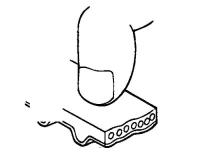
Fig. 2.211. Checking belt hardening
The back side of the belt becomes shiny and so hard that a fingernail, when pressed, leaves no mark on it (Fig. 2.211).
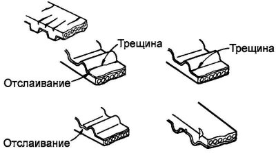
Fig. 2.212. Cracks and delamination on the belt surface
Cracks or peeling of the tooth coating material (Fig. 2.212).
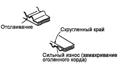
Fig. 2.213. Side surface wear
The side surface of the belt is worn (Fig. 2.213).
Note: A normal belt should have clearly defined sidewall edges, similar to knife-cut surfaces.
Severe wear of teeth.
Initial stage: the coating on the loaded side of the belt teeth is worn out (the thread base of the coating is frayed, the rubber base is exposed, the color of the belt has changed to colorless, the structure of the thread base is unclear).
The final stage: the coating is completely worn out and the rubber base on the loaded side of the belt teeth is exposed (the tooth thickness decreases).

Fig. 2.214. Checking the tensioner roller
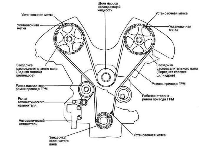
Fig. 2.215. Timing belt contour
Check the ease and smoothness of rotation of the timing belt tensioner roller and guide roller, and make sure there is no excessive play or extraneous noise when rotating. Replace if necessary (Fig. 2.214).
Installation
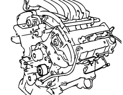
Fig. 2.216. Installing the guide roller
Install the belt guide roller into the coolant pump bosses (Fig. 2.216).
Note: The roller guide pin must be fully seated in the boss.
Install the automatic tensioner lever together with the washer onto the cylinder block.
Install the automatic tensioner roller onto the lever.
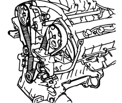
Fig. 2.217. Installing sprockets
Install the camshaft sprockets and align the timing marks with the reference marks (Fig. 2.217).
Note: When tightening the camshaft sprocket mounting bolts, hold the shaft from turning by the hexagon of the shaft
If the timing marks on the camshafts do not match the reference marks, turn the shaft in the desired direction, but not more than three sprocket teeth, since then the valve and piston come into contact.
If more than three teeth need to be turned, turn the crankshaft counterclockwise approximately 45 degrees. Carefully turn the camshaft and return the crankshaft to its original position.
Install the automatic tensioner.
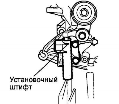
Fig. 2.218. Mounting pin
Caution! Before installation, secure the automatic tensioner pusher in the housing with a suitable pin (Fig. 2.218).
Check that all the timing marks are aligned with the reference marks and put the belt on in the following sequence:
Crankshaft - Idler Pulley - Left Camshaft - Coolant Pump - Right Camshaft - Tensioner Pulley
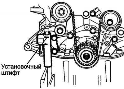
Fig. 2.219. Removing the mounting pin
Remove the automatic tensioner push rod retaining pin (Fig. 2.219).
Install the upper and lower timing belt covers
Install the power steering pump and crankshaft pulleys, tensioner pulley and idler pulley.
Using a 16 mm wrench, turn the automatic drive belt tensioner lever clockwise approximately 14 degrees and put the belt on.
Install the engine cover.
Checking the timing belt tension
Turn the crankshaft two revolutions clockwise until the piston of the first cylinder is set to TDC of the compression stroke. Pause for five minutes.
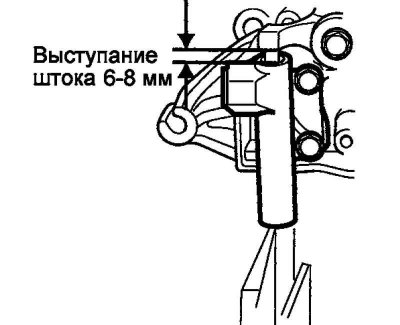
Fig. 2.220. Pusher clearance
Measure the protrusion of the automatic tensioner push rod. The protrusion should be within 6–8 mm (Fig. 2.220).
Check that all installation marks are aligned with the reference marks.
Note: If the marks do not align, repeat the timing belt installation procedure.