
Contents: Removal ⇓ Checking the oil pump housing ⇓ Checking the pressure reducing valve…⇓ Checking the oil filter bracket ⇓ Checking the oil pressure switch…⇓ Installation ⇓
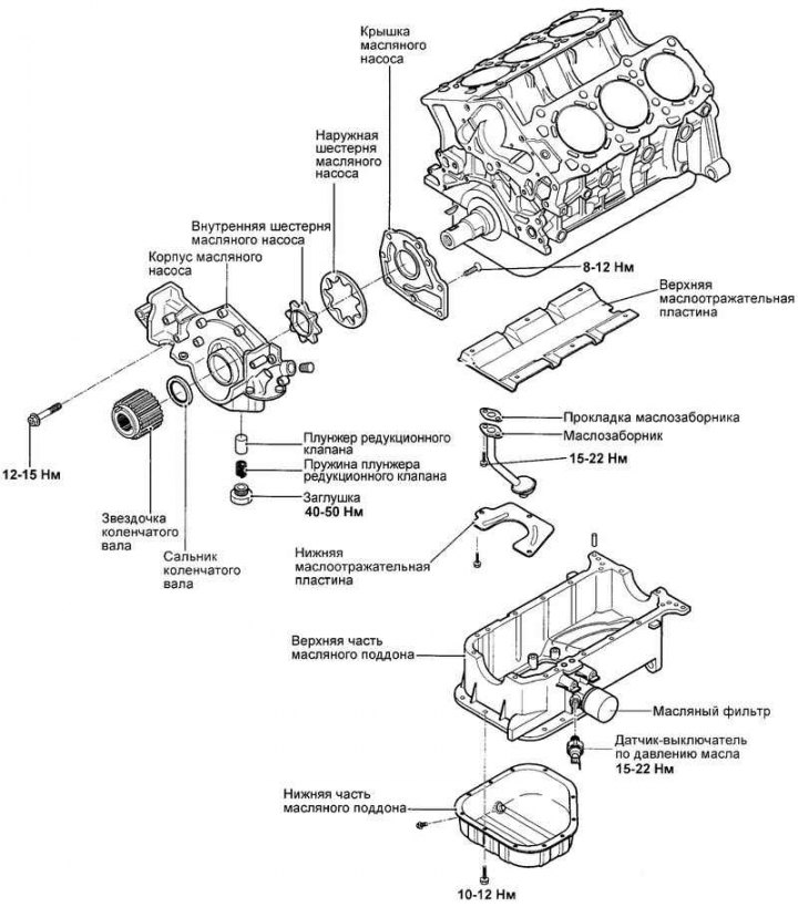
Fig. 2.313. Oil pump components
Removal
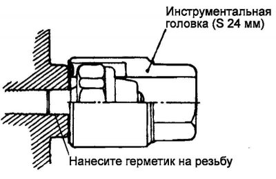
Fig. 2.314. Removing the switch sensor
Using a 24 mm tool head, unscrew the oil pressure switch (Fig. 2.314).
Note: The sensor is installed with sealant, be careful not to damage the sensor.
Remove the oil filter and oil pan.
Remove the oil pick-up.
Loosen the three mounting bolts and remove the oil filter bracket and gasket.
Unscrew the plug of the pressure reducing valve, remove the spring and plunger.
Remove the oil pump housing assembly.
Checking the oil pump housing
Check the oil pump housing for cracks or damage. Replace if necessary.
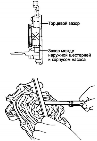
Fig. 2.315. Measuring oil pump clearances
Measure the clearance between the outer surface of the outer gear and the pump body (Fig. 2.315).
Measure the end clearance of the gears.
Oil pump clearances.
Nominal value:
- clearance between the outer surface of the outer gear and the pump body - 0.100–0.181 mm;
- end gap - 0.040–0.095 mm.
Checking the pressure reducing valve and spring
Check the ease of movement of the relief valve plunger in the oil pump housing.
Check the condition of the pressure reducing valve spring (no breakage or deformation).
Checking the oil filter bracket
Check for damage to the oil filter mating surface
Check for cracks and signs of oil leaks.
Checking the oil pressure switch sensor
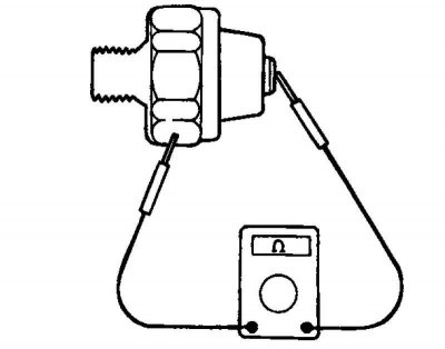
Fig. 2.316. Checking for a closed circuit between the terminal and the body of the sensor-switch
Using an ohmmeter, check for a closed circuit between the terminal and the body of the sensor-switch. If the circuit is open, replace the sensor-switch (Fig. 2.316).
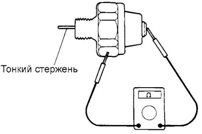
Fig. 2.317. Checking for a closed circuit using a thin rod
Insert a thin rod (or wire) into the hole of the sensor-switch and push it slightly inward. If the circuit is closed between the terminal and the body of the sensor-switch when the rod is inserted, replace the sensor-switch (Fig. 2.317).
If the circuit between the terminal and the body of the sensor-switch is open when a vacuum of 50 kPa acts on the diaphragm of the sensor-switch through the hole, then the sensor-switch is in good condition. If the vacuum is not maintained, then the diaphragm is damaged. Replace the sensor-switch.
Sensor response pressure.
Oil pressure switch: 20–40 kPa.
Installation
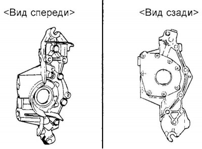
Fig. 2.318. Oil pump housing
Install the oil pump housing assembly onto a new gasket (Fig. 2.318).
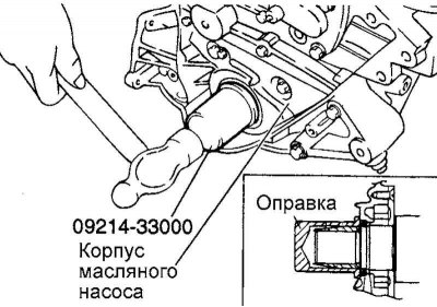
Fig. 2.319. Installing the crankshaft oil seal
Using a mandrel (09214-33000) install the crankshaft oil seal (until it stops against the wall of the socket) (Fig. 2.319).
Install the plunger and spring of the pressure reducing valve. Tighten the plug to the rated tightening torque.
Tightening torque of the pressure reducing valve plug: 40–50 Nm.
Install the oil pickup onto the new gasket.
Tightening torque of oil intake mounting bolts: 15–22 N·m.
Clean the mating surfaces of the block and oil pan.
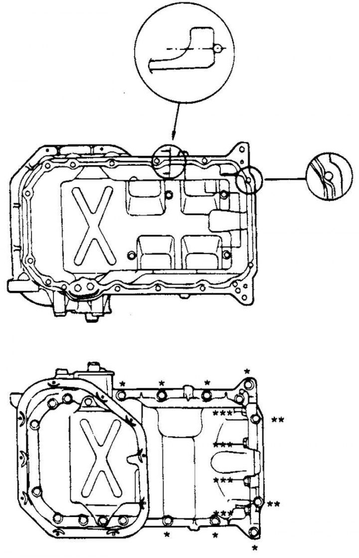
Fig. 2.320. Scheme of applying sealant to the pallet flange
Apply a bead of sealant into the groove of the pan flange (Fig. 2.320).
Note: Trim the nozzle of the sealant tube so that the diameter of the sealant bead is approximately 4 mm. The tray must be installed within 15 minutes after applying the sealant.
Note: Do not allow any sealant to get inside the tray.
Install the oil pan and tighten its mounting bolts to the specified torque.
Tightening torque of oil pan mounting bolts:
- * - 19–28 Nm;
- ** - 5–7 Nm;
- *** - 30–42 Nm.
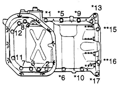
Fig. 2.321. Oil pan mounting bolt tightening sequence
The order of tightening the pan mounting bolts is shown in Figure 2.321.
Apply sealant to the threads of the oil pressure switch sensor and tighten the sensor to the specified torque.
Three Bond Sealant No.1141E or 3M ATD No.8660 or equivalent.
Note: Do not exceed the rated tightening torque of the sensor.
Tightening torque of the oil pressure switch: 15–22 N·m.
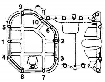
Fig. 2.322. Tightening order of the lower tray mounting bolts
Tighten the lower pan mounting bolts in the order shown in Figure 2.322.