
Contents: Disassembly ⇓ Checking the crankshaft ⇓ Main and connecting rod bearing…⇓ Measuring bearing clearance ⇓ Measuring bearing clearance using a…⇓ Checking the seal ⇓ Automatic transmission drive plate ⇓ Assembly ⇓
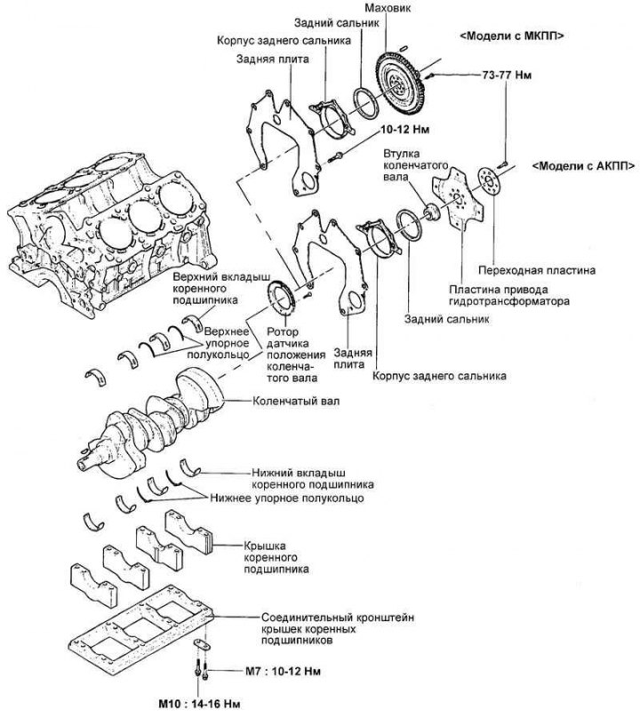
Fig. 2.280. Crankshaft and its components
Disassembly
Remove the timing belt, front cover, flywheel, cylinder head and oil pan. Refer to the appropriate sections for part removal procedures.
Remove the rear plate of the cylinder block and the rear crankshaft oil seal.
Remove the connecting rod caps and connecting rod bearing shells.
Note: For proper subsequent installation, arrange the removed parts (connecting rod caps, connecting rod and main bearing shells) in the order of their cylinder numbers and orientation at the installation location.
Remove the main bearing cap connecting bracket, main bearing caps and crankshaft. Arrange the main bearing shells in order of their cylinder numbers.
Checking the crankshaft
Check the crankshaft main and connecting rod journals for damage (scoring and seizure), excessive wear and cracks. Clean the shaft oil passages. Repair or replace the crankshaft if necessary.
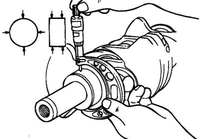
Fig. 2.281. Checking the taper and ovality of the main and connecting rod journals of the crankshaft
Check the taper and ovality of the main and connecting rod journals of the crankshaft (Fig. 2.281).
Nominal value:
- Main journal diameter: 61.982–62.000 mm.
- Crankpin diameter: 47.982–48.000 mm.
Main and connecting rod bearing shells
Visually inspect the surface condition of each bearing (peeling of the friction layer, uneven contact, scratches, scoring, etc.). Replace defective bearings.
Measuring bearing clearance
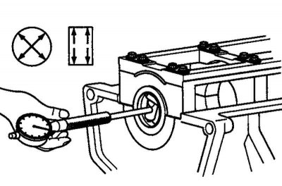
Fig. 2.282. Measuring the internal diameters of the main bearing holes
Measure the diameter of the main and connecting rod journals of the crankshaft. Measure the internal diameters of the holes for the main bearings in the crankshaft bed (in the cylinder block and bearing cap) and the holes for the connecting rod bearings (in the lower connecting rod head and connecting rod cap) (Fig. 2.282).
Measure the thickness of the connecting rod and main bearing shells. Calculate the bearing clearance based on the measurements taken (subtract the shaft journal diameter and two bearing shell thicknesses from the internal diameter of the bearing hole).
Nominal value:
- Main bearing clearance: 0.004–0.022 mm.
- Connecting rod bearing clearance: 0.018–0.036 mm.
Limit clearance: 0.1 mm.
Measuring bearing clearance using a plastic gauge
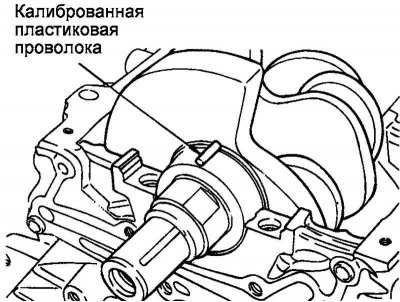
Fig. 2.283. Installing a plastic gauge
Determining the clearance value in the main bearings of the crankshaft using the plastic gauge method.
Remove oil, grease or other contaminants from the shaft journals. Wash and dry the bearing shells.
Cut the plastic gauge into pieces equal in width to the shaft journals. Place the gauges on the journals along the shaft axis (do not place the gauge on the oil supply holes).
Install the bearing shells, crankshaft and main bearing cap connecting bracket. Tighten the main bearing cap connecting bracket mounting bolts to the rated tightening torque. Do not rotate the crankshaft! Remove the connecting bracket. Measure the maximum width of the crushed portion of the gauge using the scale on the gauge envelope. Determine the bearing clearance. If necessary, repair or replace the crankshaft or bearing shells. If replacing the shell does not correct the clearance, regrind the shaft journals to the repair size and replace the shells accordingly.
Checking the seal
Check the front and rear crankshaft oil seals for damage or wear on the working edges. If there are any defects, replace the oil seal.
Automatic transmission drive plate
Replace any warped or cracked plate.
Assembly
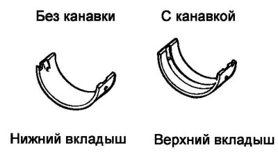
Fig. 2.284. Upper and lower main bearing shells
Install the upper main bearing shells into the crankshaft bed on the cylinder block (Fig. 2.284). The upper shells have an oil distribution groove.
Install the lower bearing shells (without grooves) into the main bearing cap connecting bracket bed.
Apply engine oil to the crankshaft main journals. Install the crankshaft.
Install the lower bearing shells and main bearing caps with the mark facing the front of the engine.
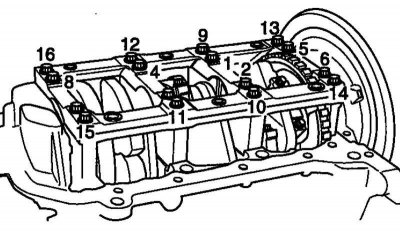
Fig. 2.285. Tightening order of main bearing cap bolts
Tighten the cover mounting bolts to the rated tightening torque (Fig. 2.285).
Tightening torque of the main bearing cap bolts: M7 (9–16) – 10–12 N·m, M10 (1–8) – 14–16 N·m.
Tighten the bolts gradually in four to five steps, then tighten to the specified torque.
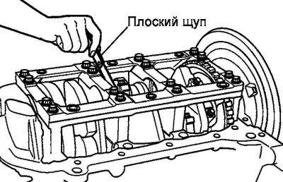
Fig. 2.286. Measuring the axial clearance of the crankshaft
Check the freedom of rotation of the crankshaft and measure the axial clearance (Fig. 2.286).
Axial clearance:
- Nominal value: 0.07–0.25 mm.
- Limit value: 0.4 mm.
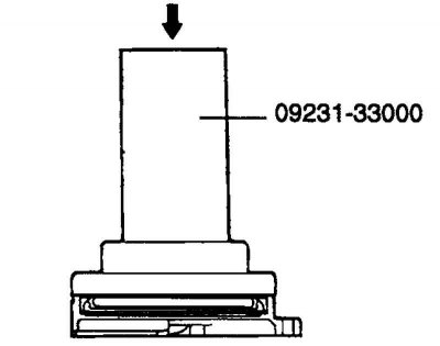
Rice. 2.287. Mandrel for installing the oil seal
Using a mandrel (09231–33000) install the seal into its housing (Fig. 2.287).
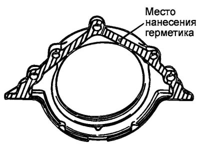
Fig. 2.288. Places of sealant application
Apply sealant to the areas of the seal housing shown in the figure (Fig. 2.288). Install the housing and seal.
Tightening torque of the rear oil seal housing mounting bolts: 10–12 N·m.
Install the rear plate of the cylinder block and tighten its mounting bolts.
Tightening torque of rear plate mounting bolts: 10–12 Nm.
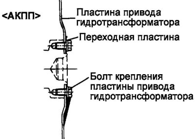
Fig. 2.289. Hydraulic transformer plate installation diagram
Models with automatic transmission: Install the automatic transmission drive plate and adapter plate (Fig. 2.289).
Tightening torque of plate mounting bolts: 73–77 N·m.
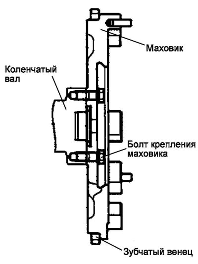
Fig. 2.290. Flywheel installation diagram
Models with manual transmission: install the flywheel. Tighten the mounting bolts to the rated torque (Fig. 2.290).
Tightening torque of plate mounting bolts: 73–77 N·m.