
Contents: Removal ⇓ Checking the cylinder head ⇓ Checking the valve guides ⇓ Checking the valves ⇓ Checking valve springs ⇓ Valve seat restoration ⇓ Replacing the valve guide bushing ⇓ Replacing the valve seat ⇓ Assembly ⇓
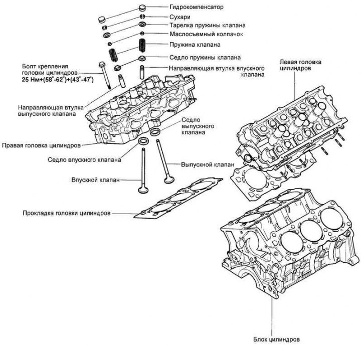
Fig. 2.249. Cylinder head, valves and valve springs
Removal
Drain the coolant and disconnect the upper radiator hose.
Disconnect the air ducts and crankcase ventilation hose.
Disconnect the vacuum, fuel and water hoses.
Remove the intake manifold.
Disconnect the spark plug wires from the spark plugs. Pull the protective cap, not the wires themselves.
Remove the ignition coil.
Remove the timing belt covers.
Remove the timing belt and camshaft sprockets.
Remove the exhaust manifold covers and the exhaust manifolds themselves.
Remove the coolant pump pulley and valve covers.
Remove the camshafts.
Loosen the cylinder head mounting bolts in two or three steps (12 mm tool head). Remove the cylinder head.
Remove any remaining old gasket from the mating surfaces of the cylinder head and block.
Note: Take care to prevent dirt from entering the engine crankcase.
Checking the cylinder head
Check the cylinder head for cracks, damage, and signs of coolant leakage. If cracks are found, replace the cylinder head.
Completely clean the cylinder head from scale, carbon deposits and remnants of old sealant and gasket. Clean the oil passages, blow them out with compressed air.
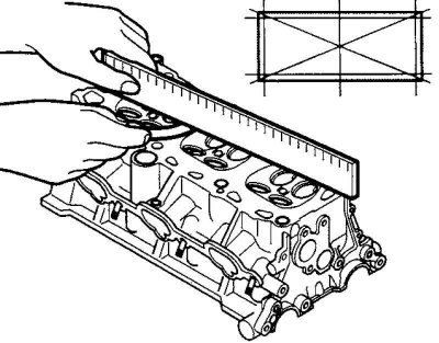
Fig. 2.250. Checking the non-flatness of the mating surface of the cylinder head
Check the non-flatness of the cylinder head mating surface in the directions shown in Figure 2.250.
Non-flatness of the cylinder head mating surface:
Nominal value: less than 0.03 mm.
Maximum permissible value: 0.05 mm.
Checking the valve guides
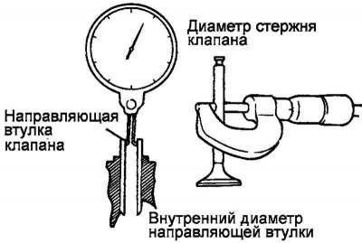
Fig. 2.251. Checking the clearance between the valve guide and the valve stem
Check the clearance between the valve guide and the valve stem (at several points along the length). If the clearance is greater than the maximum permissible value, replace the valve guide (Fig. 2.251).
Clearance between the guide and the valve stem.
Nominal value:
- inlet valve: 0.02-0.05 mm;
- exhaust valve: 0.035–0.065 mm.
Maximum permissible value:
- inlet valve: 0.10 mm;
- outlet valve: 0.15 mm.
Checking the valves
Inspect each valve for wear, damage or deformation of the valve disc and the "B" area of the valve stem. Replace the valve if necessary. If the "A" end of the valve stem is dented or significantly worn, replace the valve.
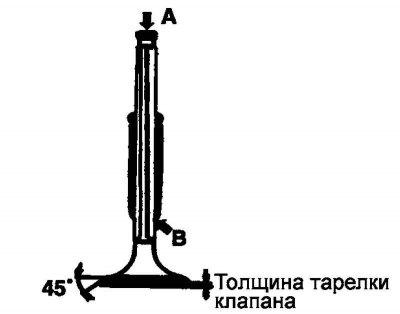
Fig. 2.252. Valve testing diagram
Check the condition of the valve shut-off chamfer and restore if necessary (Fig. 2.252).
Replace the valve if the valve plate thickness is less than the maximum allowable value
Valve plate thickness.
Nominal value:
- Inlet valve - 1.0 mm;
- Exhaust valve - 1.3 mm.
Maximum permissible value:
- Inlet valve - 0.5 mm;
- Exhaust valve - 0.8 mm.
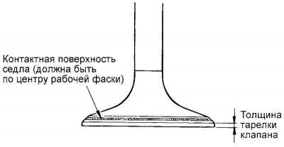
Fig. 2.253. Contact check of the valve seat
Checking valve springs
Check the free length of the valve spring. If the spring length is less than the maximum permissible value, replace the valve spring.
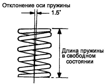
Fig. 2.254. Valve spring testing diagram
Using a square, check the deviation of the spring axis from the perpendicular to the support surface (non-perpendicularity). If the non-perpendicularity is greater than the maximum permissible value, replace the valve spring (Fig. 2.254).
Valve spring.
Nominal value:
- spring length in free state - 42.5 mm;
- spring length under load 21.9 kg - 35.0 mm;
- spring axis deviation (non-perpendicularity) - 1.5° or less.
Maximum permissible value:
- spring length in free state - 41.5 mm;
- spring length under load 21.9 kg - 34.0 mm;
- spring axis deviation (non-perpendicularity) - 3°.
Valve seat restoration
Check the valve seat for signs of overheating and uneven contact with the valve disc locking chamfer. If necessary, either restore or replace the valve seat.
Before reconditioning the valve seat, check the valve guide for wear. If the guide is worn, replace it first, then recondition the valve seat.
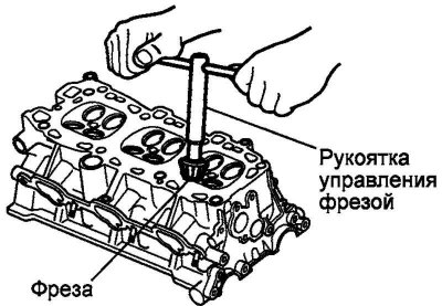
Fig. 2.255. Restoring the valve seat
The valve seat is restored using a special tool (milling cutters or machine tools). After the valve seat has been restored, the valve and valve seat must be lapped using lapping paste (Fig. 2.255).
Replacing the valve guide bushing
Using a special tool (valve guide installation tool 09221-29000), press the old valve guide out of the cylinder head towards the gasket surface.
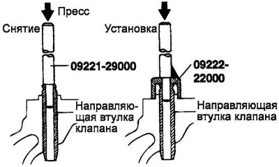
Fig. 2.256. Valve guide bush replacement diagram
Ream the cylinder head hole to install a valve guide bushing of the appropriate repair size (increased diameter) (Fig. 2.256).
Using a special tool (mandrel for installing the valve guide bushing 09221-29000 (A), 09222-22000 (B)) press in a new valve guide bushing.
The guide bushing should be pressed in from the side of the camshaft bed. Note the difference in length between the guide bushings for the intake and exhaust valves.
After installing the valve guide, insert the new valve and check that the clearance between the guide and the valve stem is within the specified value.
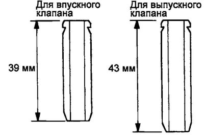
Fig. 2.257. Length of valve guide bushings
After replacing the valve guide bushing, check that the valve is seated correctly in the seat. If necessary, treat the valve seat (Fig. 2.257).
Note: Do not install the old size guide, always ream the head to the next repair guide size.
Replacing the valve seat
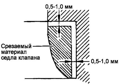
Fig. 2.258. Valve seat replacement diagram
Cut out the valve seat to be replaced, the residual amount of metal is shown in Figure 2.258.
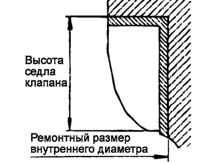
Fig. 2.259. Diagram of boring a hole in a cylinder head
Ream the hole in the cylinder head to install a valve seat of the appropriate repair size (increased diameter) (Fig. 2.259).
Heat the cylinder head to approximately 250°C and press the oversize seat into the cylinder head.
Lapping the valve to the new seat using lapping paste.
Valve seat chamfer width:
- inlet - 1.1–1.5 mm;
- release - 1.3-1.7 mm.
Assembly
Install the valve spring seats.
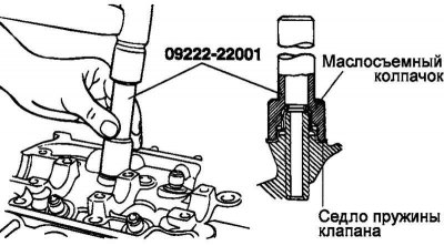
Fig. 2.260. Installation diagram of the oil scraper cap
Using a special tool (mandrel for installing the oil seal 09222-22001), lightly tap the oil seal into place (Fig. 2.260).
Note: Reusing valve stem seals is not permitted.
Note: Incorrect installation of the valve stem seal may result in oil leaks through the valve guide.
Lubricate the valve stem with engine oil. Insert the valve into the valve guide. Do not force the valve stem through the valve stem seal. After installing the valve, check for smooth movement.
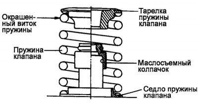
Fig. 2.261. Valve spring installation diagram
Install the valve spring so that the painted spring coil is located near the spring plate (top), and then install the valve spring plate (Fig. 2.261).
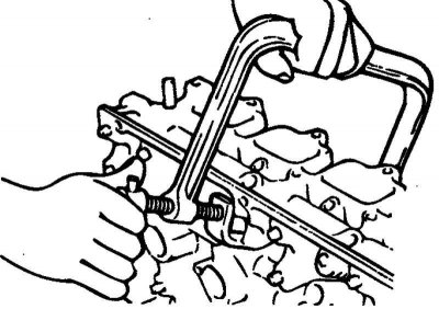
Fig. 2.262. Installing crackers
Using a special tool (valve spring compressor 09222-28000 and adapter 09222-28100), compress the valve spring and install the crackers. Before removing the special tool after installing the valve, check the reliability of the crackers (Fig. 2.262).
Note: When compressing the valve spring, make sure that the spring plate does not touch the valve stem seal.
Clean the mating surfaces under the gasket on the cylinder head and cylinder block.
Check that the cylinder head gasket identification marks match the technical data.
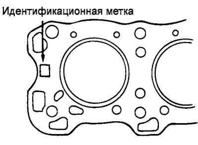
Fig. 2.263. Cylinder head gasket identification mark
Install the cylinder head gasket on the cylinder block with the identification mark facing up (towards the cylinder head) (Fig. 2.263).
Note: Do not apply sealant to the gasket.
Tighten the cylinder head mounting bolts to the specified torque in the order shown in Figure 2.264.
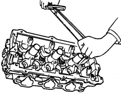
Fig. 2.264. Tightening the cylinder head mounting bolts
When tightening bolts (12 mm tool head), a combined tightening method (torque + angular rotation) is used (Fig. 2.264).
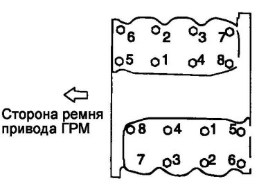
Fig. 2.265. Cylinder head bolt tightening sequence
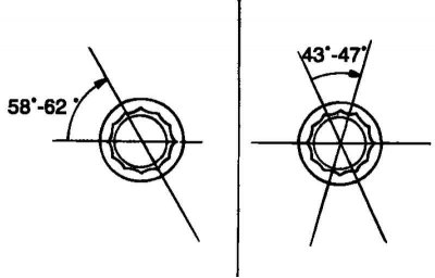
Fig. 2.266. Scheme for turning the cylinder head mounting bolts
Tightening torque of cylinder head bolts: 25 Nm + (58–62°)+ (43–47°) (Fig. 2.266).